
ABS Encoders in Wheel Hub Bearings: Specification and Handling
A wheel hub bearing with an ABS encoder must match both the mechanical wheel end and the vehicle’s wheel-speed sensing arrangement. The encoder, sensor, mounting orientation and electrical interface form a system. A bearing can look correct and still be unsuitable if one of those details differs. For distributors and technical buyers, the useful question is therefore specific: what evidence identifies the required assembly, and what checks will confirm that the delivered part matches it?
This guide explains the terms used in hub-bearing enquiries, the information to request, and a practical receiving workflow. It is intended for specification and purchasing decisions. Vehicle-specific installation instructions remain the authority for fitting, wiring, tightening and diagnostic procedures. No universal pole count, sensor gap or tightening value applies to every wheel hub bearing.
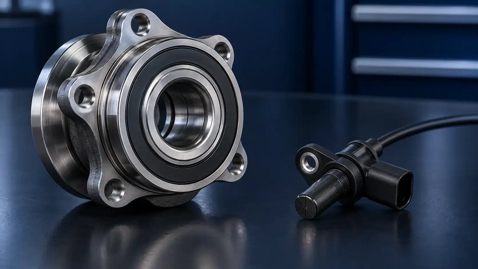
Separate the encoder, sensor and bearing
The magnetic encoder is the rotating target used by a compatible sensing system. The wheel-speed sensor detects changes from that target and supplies information to the vehicle electronics. The bearing supports relative rotation and load. These functions may be packaged closely together, but the names should remain separate in a quotation.
Some wheel-end arrangements use a toothed reluctor rather than a multipole magnetic ring. Other arrangements incorporate an encoder in a bearing seal. Calling every rotating target an ABS ring obscures these differences. NTN describes the integrated magnetic encoder and active sensor arrangement in its ASB technology overview. That description explains the technology, not compatibility between unrelated products.
A supplier’s statement that a hub is “ABS compatible” does not tell a buyer whether the sensor is included. The quotation should identify the rotating target, any supplied sensor and harness, and the accessories included in the package. If a sensor remains on the vehicle, record the interface requirements against that existing system. If a sensor comes with the hub, verify its connector and routing as well as the mechanical mounting.
| Term in an enquiry | Detail that should be clarified | Evidence to request |
|---|---|---|
| ABS bearing | Target technology and location | Product drawing or application record |
| Magnetic encoder | Orientation and specified signal characteristics | Applicable specification and inspection method |
| Sensor included | Sensor reference, connector and cable arrangement | Bill of materials and labelled photographs |
| Hub assembly | Mounting interfaces and supplied hardware | Controlled drawing and kit list |
| Direct replacement | Exact vehicle variant and installation position | Traceable fitment confirmation |
Establish the application before checking the encoder
Start with the original reference, vehicle configuration and wheel position. Keep the reference exactly as supplied, including suffixes and leading zeros. Record whether it came from the removed component, an original equipment catalogue, an aftermarket catalogue or a previous order. Those sources have different roles and should not be silently combined into one approved number.
Make, model and year can leave important questions unanswered. Add the market, drivetrain and other identifying information required by the applicable catalogue. A front driven wheel end and a rear non-driven wheel end may have different mechanical and sensing arrangements even within one model family. Where the application is uncertain, put the uncertainty in the enquiry instead of choosing the closest-looking photograph.
Review the bearing and hub interfaces alongside the sensing requirements. The wheel hub flange dimension guide explains the distinction between mounting faces, pilots and bolt patterns. A matching connector cannot compensate for a different mounting interface. Equally, matching flange dimensions do not establish a correct sensor target.
Build a specification that another person can check
A useful specification describes the assembly without relying on an experienced buyer’s memory. Begin with a unique enquiry-line identifier, then connect the supplier’s proposed part number to the original reference and intended application. Add the drawing revision and the date of the supplier’s confirmation. This creates a clear record if the product or catalogue changes later.
List the encoder-related fields separately from dimensional fields. Include the target type, its location, the specified orientation and any signal characteristics that the responsible engineer requires. Enter a pole count only when an authoritative source supplies it. Do not estimate it from an illustration or borrow a value from a similar bearing. A blank field marked “confirmation required” is more useful than an unsupported number.
For sensor-equipped assemblies, include connector photographs from more than one angle, mounting details, cable protection and the supplied clip arrangement. Photographs help identify differences, but they do not replace an electrical specification. Where a functional test is needed, agree who will perform it and what equipment, reference configuration and acceptance criteria will be used.
Confirm orientation without making visual assumptions
A dark seal is not sufficient proof that a surface is magnetically encoded. Confirm the encoder side using product-specific documentation and, where appropriate, a suitable viewing tool. The relationship between the encoder and sensor must follow the intended wheel-end design. Avoid converting an instruction for one bearing family into a universal rule such as “the black side always faces inward.”
NSK’s magnetic encoder wheel-bearing replacement guidance illustrates why encoder orientation and correct tools matter. The practical purchasing implication is to request an identifiable orientation reference before a batch reaches the workshop, rather than expecting each installer to infer it from seal colour.
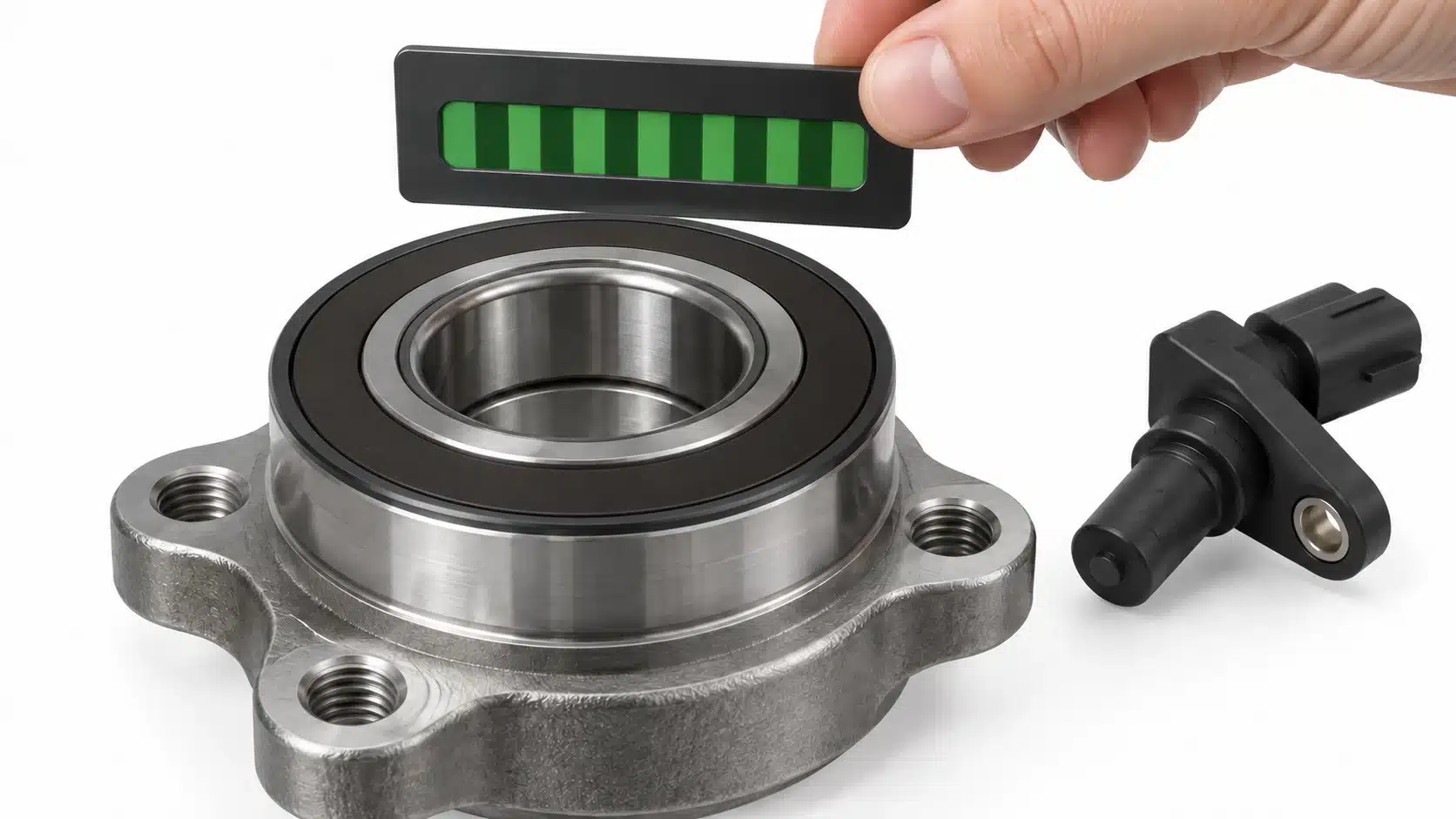
A magnetic viewing card can make a pattern visible and help identify the encoded side. Its use should follow the tool and component instructions. A visible pattern is not a complete electrical compatibility test, nor does it establish correct performance with every sensor. Treat it as one observation within the inspection plan, and record what it actually demonstrated.
Receive the part without creating the defect
Receiving inspection should begin while the packaging still preserves identification and condition. Photograph the label and any shipping damage, then connect the package to the purchase-order line and lot record. Open only the number of packages required by the agreed inspection plan. Keep loose metallic debris, cutting tools and unrelated parts away from the inspection surface.
Check for obvious impact marks, damaged protective covers, distorted seals and trapped particles without scraping the encoder face. NTN’s ASB handling instructions specifically address shocks, metallic contamination and magnetic exposure. Use the limits and precautions applicable to the supplied product; there is no reason to invent a general workshop magnet test.
Separate observation from disposition. “Visible dent on encoder-side seal” is an observation. “Rejected under the agreed appearance requirement” is a disposition supported by a requirement. “Manufacturing fault” is a causal conclusion requiring additional evidence. Keeping those statements distinct makes a complaint easier to investigate and reduces unnecessary disagreement between purchasing, stores and the supplier.
For repeat deliveries, compare the received identity and revision with the approved reference. A familiar box design should not bypass checks. Packaging, a sensor supplier or a connector can change without a conspicuous change in the marketing description. Ask that relevant changes be declared before shipment and routed through the same approval process used for the original sample.
Agree what a functional check must demonstrate
An encoder inspection can answer several different questions: is the correct target present, is it physically intact, is the assembly identified correctly, and does the intended sensing arrangement produce an acceptable output? A single result labelled “ABS test passed” does not reveal which of those questions was tested.
Before commissioning a functional check, define the product reference, sensor or test fixture, operating conditions and output to be evaluated. The test method should identify any power supply, rotational conditions and signal-processing assumptions that affect the result. Acceptance limits must come from an approved specification, not from a generic blog or a comparison with an unrelated hub.
Ask for the sample identity and the date of the result. If the test is performed on a retained reference assembly, establish how production units are linked to that reference. If only a small sample is tested, describe the sampling scope accurately. A successful sample evaluation supports that evaluation; it is not a statement that every delivered unit has been tested in a vehicle.
The broader wheel hub bearing inspection plan provides a way to combine identity, dimensions and functional records. Keeping these checks in one controlled plan helps purchasing request the evidence that matters without demanding unrelated tests simply because their names sound rigorous.
Investigate an ABS warning in a useful sequence
An ABS warning appearing after hub replacement deserves diagnosis, but timing alone does not establish a defective encoder. Request the diagnostic trouble codes, the affected wheel position, the fitted reference and the circumstances in which the warning appeared. Preserve the old and new component identities where available. The workshop should investigate according to the vehicle manufacturer’s procedure.
For the supplier discussion, organise the evidence into three groups. First, identity: was the approved part actually supplied and fitted? Second, assembly: were the orientation, mounting and harness arrangements correct? Third, function: what do the appropriate diagnostic observations show? This sequence prevents an early assumption from controlling the whole investigation.
Do not ask a customer to carry out an improvised road test or continue driving to collect symptoms. A qualified workshop can decide the appropriate diagnostic method and whether the vehicle is safe to move. The distributor’s role is to obtain accurate records, provide the agreed product information and coordinate the technical response.
| Reported observation | Useful follow-up | Conclusion to avoid |
|---|---|---|
| Warning after installation | Trouble codes, reference and fitting record | Every new warning proves a bad bearing |
| Connector differs | Photographs and approved connector requirement | A modified connector is automatically acceptable |
| Pattern visible on viewing card | Orientation record and required functional test | Pattern visibility proves full compatibility |
| Encoder surface damaged | As-received and installation photographs | Damage must have occurred at one particular stage |
| Intermittent wheel-speed reading | Qualified diagnostic record and operating conditions | A guessed pole count explains every fault |
Package encoder-equipped bearings for the real handling route
Packaging should protect the sensing surface and keep the part identifiable through receiving, storage and workshop delivery. Request an arrangement that prevents adjacent metal components from striking sensitive surfaces. A protective cap or separator should be described in the packing specification if it is part of the approved solution. Do not assume every catalogue image shows the shipping configuration.
Where sensor cables are included, agree how the harness is restrained and how the connector is protected. A cable wound tightly around studs or used as a lifting point can create a handling problem unrelated to the bearing’s mechanical quality. Packaging photographs should show the packed product, not only an attractive closed carton.
Labels can communicate the product number, lot and handling information, but they should not replace fitting instructions. Keep any orientation illustration associated with the correct reference and revision. If instructions are translated, preserve the technical meaning and have the relevant terminology checked before the translated insert becomes part of a repeat order.
Turn unresolved details into an actionable enquiry
An effective enquiry names the question that blocks approval. Instead of writing “please confirm ABS,” specify that the buyer needs the encoder location confirmed, a connector photograph, or a test record linked to a sample. Assign each question to an enquiry line so that a reply cannot accidentally apply to several similar references.
For the commercial handover, the Huayuan wheel hub bearing RFQ checklist provides a complementary purchasing structure covering quantities, packaging and written quotation terms. Use it to organise the request after the technical requirements are clear. Technical compatibility and commercial availability remain separate confirmations.
When reviewing JNHJDP wheel hub bearings, send the original reference, application, position and encoder questions with the enquiry. For a complete unit, use the wheel hub assembly category and identify the required kit contents. The contact team can then review a defined request rather than a collection of ambiguous part photographs.
Questions buyers often ask
Does every ABS wheel hub include a wheel-speed sensor?
No. Describe the supplied assembly precisely. A bearing may contain a magnetic target while the sensor remains a separate vehicle component. Ask for the bill of materials and confirm whether a harness, clips or other accessories are included. The answer should apply to the quoted reference, not merely to the product family.
Can a bearing with the same dimensions use a different encoder?
Matching dimensions alone cannot establish sensing compatibility. Review the application, target arrangement and required functional characteristics independently. Where a supplier proposes an alternative, keep the change visible and obtain the appropriate technical confirmation before treating it as interchangeable.
Should purchasing staff count poles from a generated diagram?
No. An illustration explains a concept and cannot establish a product specification. Obtain encoder requirements from the applicable technical record. The images on this page are conceptual illustrations, not photographs of an approved sample or evidence of a particular encoder design.
What belongs in the final approval file?
Keep the original request, agreed product reference, application evidence, current drawing, encoder and sensor requirements, sample results, packaging approval and unresolved exceptions. Record who approved each decision. That compact file makes a later repeat order or investigation much easier than searching through disconnected messages.