Proper Wheel Bearing Installation: Technician Guide
Correct installation protects the new bearing from damage that may be invisible at the time of repair. The exact vehicle service procedure controls; the technician must also verify fitment, support the interference-fit ring, prepare mating surfaces, use specified hardware and record final torque and signal checks.
How do you install a wheel bearing without damaging it?
Confirm the exact application and encoder orientation, use clean correctly sized tools, and apply press force only through the ring with the interference fit. Prepare and inspect the knuckle, axle and mounting faces; replace specified one-time fasteners; tighten hub and axle hardware with the current vehicle torque/angle procedure and calibrated tools. Complete rotation, play/runout, brake, wiring, ABS and road checks before release.
The four installation principles that protect a wheel bearing
First, confirm the exact part and wheel position before disassembly. Second, keep force out of the rolling elements: support the ring that has the interference fit. Third, prepare every mating surface and replace specified one-time hardware. Fourth, use the current vehicle procedure and calibrated tools for fastener torque, bearing setting and final verification.
These principles apply whether the job uses a pressed-in bearing, a flanged hub or a bolt-on integrated assembly, but the detailed sequence differs. Some units contain a magnetic ABS encoder that must face a particular direction. Some driven hubs rely on a specified axle-nut clamp load. Some serviceable tapered arrangements require adjustment and endplay measurement. A generic online torque table cannot safely combine them.
Installation boundary: this guide explains process control and common error mechanisms. It does not provide vehicle-specific torque, press tooling, endplay or road-test instructions. Obtain those values from the current service information for the exact vehicle.
Verify the replacement part before the vehicle is disabled
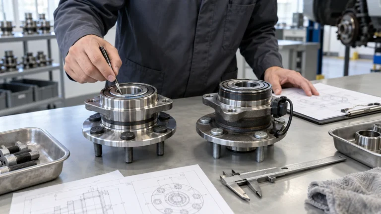
Match the OE reference and all suffixes, vehicle model and year, market, front or rear axle, left or right where differentiated, and driven or non-driven configuration. Compare the bearing or hub generation, flange pattern, mounting-hole count, wheel studs and thread, pilot, spline, overall offset, sensor or encoder, connector, cable length, clip positions and included hardware. A visual resemblance or one shared diameter is not enough.
Photograph the old part in its installed orientation before disconnecting a sensor lead or removing brackets. Mark the inboard face when an encoder cannot be seen. If a magnetic viewing tool is permitted, use it without scratching or contaminating the seal. Do not infer orientation from seal color. Check the new part for transit damage, corrosion, dented shields, damaged threads, loose studs or an unprotected connector before opening every package in the order.
If identifiers conflict, stop and resolve them. Forcing a near-match onto the vehicle can damage the knuckle, axle, sensor and new bearing, and it removes the evidence needed to correct the catalog. Buyers can structure application evidence with the HJDP OE-number RFQ guide.
Keep unopened parts in their protective packaging until the clean installation stage. Do not stack weight on sensor leads, seals or studs, and do not accept a carton whose impact damage has transferred to the hub. Quarantine mixed or unidentified parts before they reach the bay.
Record any packaging damage before use.
Do not install an unidentified component.
Prepare the work area, tools and replacement hardware
Use a lift or stands rated and positioned for the vehicle, wheel restraints and appropriate personal protective equipment. Prepare the service procedure, press or approved installer, bearing separators and support plates, pullers, seal drivers, snap-ring tools, torque wrenches that cover the required ranges, angle gauge if specified, dial indicator where required, cleaning materials and suitable supports for the brake caliper and driveshaft components.
Confirm which axle nuts, cotter pins, locking devices, retaining rings, stretch bolts and hub bolts must be replaced. A nut can appear reusable while its prevailing torque, staking feature or controlled deformation has been consumed. Keep new hardware associated with the correct kit; do not mix fasteners from a similar application. Check torque-tool calibration status and ensure sockets and extensions are suitable for the specified method.
Cleanliness matters before the package opens. Separate dirty removal tools from clean installation tooling. Keep grinding debris and magnetic particles away from encoder seals. Do not place a new bearing directly on a dirty floor, brake dust or the removed hub. Protect the product from impacts; a bearing can be damaged without visible external deformation.
Remove components without destroying diagnostic evidence
Record the complaint, wheel position and initial checks before loosening fasteners. Follow the approved sequence for wheel, brake, axle, sensor and hub removal. Support the caliper instead of hanging it by the hose. Protect the wheel-speed sensor and harness. If a puller or press is needed, react the load through designated surfaces and protect the axle threads and knuckle.
Do not use the returned part as an improvised hammer. Preserve seal damage, corrosion tracks, fretting, lubricant condition and fracture surfaces for analysis. Photograph the mounting face, bore, spline, fasteners and connector. If excessive heat or looseness was reported, inspect the brake, tire, wheel, suspension and axle interfaces rather than assuming the new hub will correct every symptom.
A seized assembly may require corrosion release methods or application-specific tooling. Excess heat can damage temper, seals, ABS components and adjacent parts. If the official procedure permits heating, control location and temperature. Otherwise escalate instead of improvising with a torch.
Inspect and prepare mating components
The knuckle bore or mounting face must be clean, undamaged and within the service limit. Remove loose rust and debris without removing base metal or changing geometry. Inspect for fretting, ovality, cracks, galling and previous tool damage. Check the hub shaft or axle spline, threads, shoulder and seal running surface. A new bearing installed on a damaged interface can fail or loosen even when the part itself is correct.
Clean brake-rotor and wheel mounting faces according to the service procedure. SKF notes that rust or contamination at the hub interface can create misalignment and runout that affects bearing and braking behavior. Do not apply paste, grease or anti-seize to a dry specified interface unless the manufacturer instructs it; lubricant changes the relationship between applied torque and clamp load.
Inspect snap-ring grooves and shields, and orient drainage or retaining features correctly. Verify that a bearing retaining ring is fully seated. Check whether the encoder side must face the sensor. Install or retain only approved shields and spacers; an omitted spacer or reversed bearing can create an immediate clamp or signal problem.
Installing a pressed-in wheel bearing
Plan the load path before operating the press. When pressing the outer ring into a knuckle, support and drive the outer ring. When pressing a hub shaft into the installed inner ring, support the affected inner ring. Sending installation force through the balls or rollers can indent the raceways and create noise, vibration and shortened life before the vehicle leaves the bay.
Use adapters that contact the intended ring squarely and do not touch seals, encoder surfaces or cages. Align the parts before force rises. Monitor press force and travel when equipment permits; an unexpected spike or low-force movement can indicate misalignment, wrong dimensions, damaged fit or missing support. Stop and investigate rather than using more force. Never hammer directly on a precision bearing or pull a hub into place with an unrelated fastener unless the procedure explicitly defines that method.
Install the retaining ring with the correct orientation and verify full engagement. If the design uses a separate seal, use the specified driver, depth and lip orientation, and protect the sealing surface. Rotate the assembly by hand after each major step when the procedure allows it. A change from smooth rotation to roughness or binding identifies the stage at which damage may have occurred.
Installing a bolt-on hub assembly
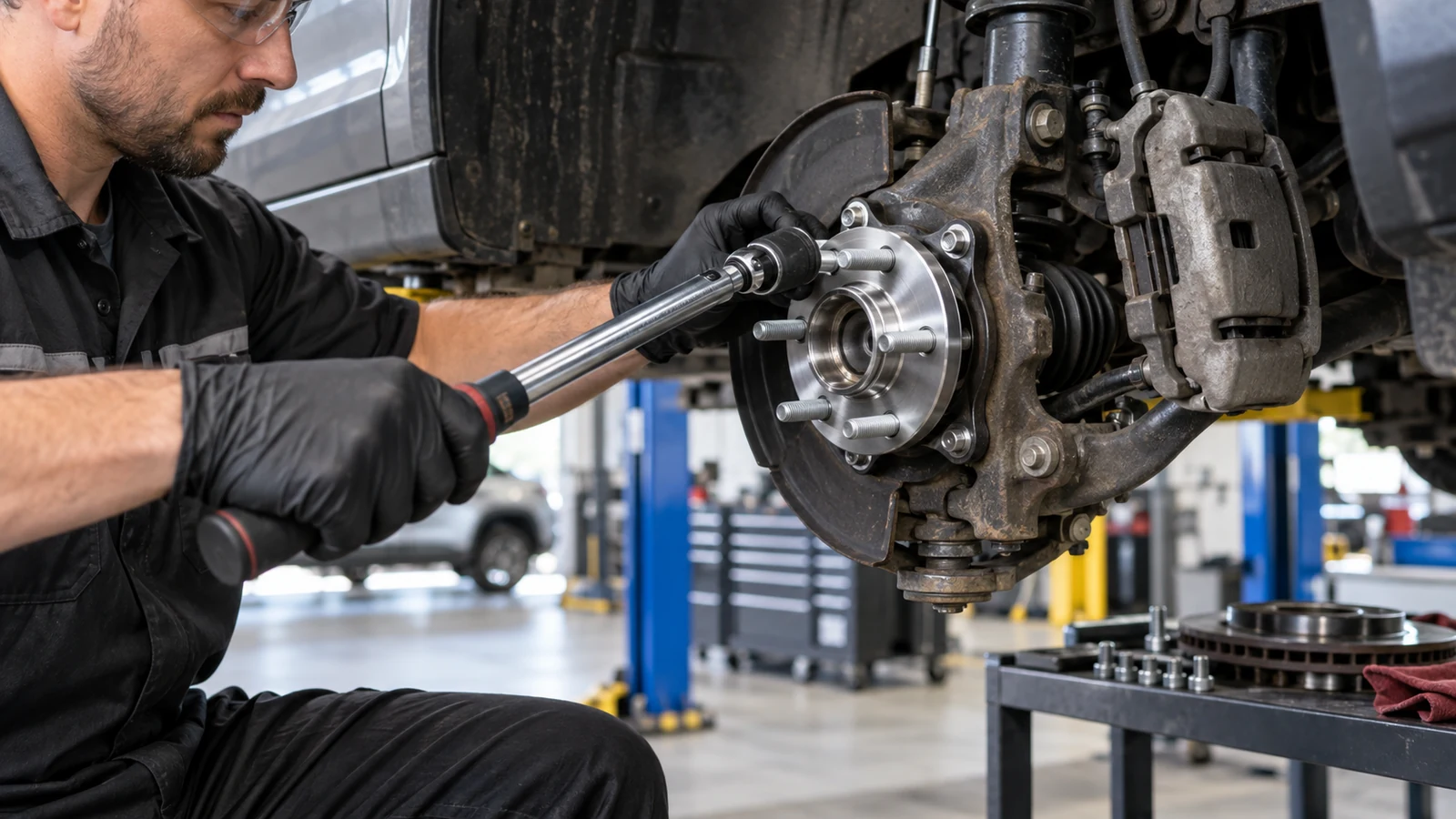
Place the hub squarely against the prepared knuckle and route any sensor lead before tightening. Start mounting bolts by hand to prevent cross-threading. Draw the assembly down evenly using the sequence and stages in the service information. Do not use one bolt to pull a cocked hub across a rusty bore. Confirm that the backing plate, dust shield and cable brackets are in their correct positions and are not trapped.
Use a calibrated torque wrench and the specified socket. Torque values depend on thread, coating, lubrication state, fastener design and application; do not copy a value from a visually similar hub. If an angle stage is specified, complete it with the proper gauge. Marking fasteners after final torque can support process verification, but a paint mark does not prove that the correct value was applied.
Reconnect the sensor without pulling or twisting the cable. Seat connector locks and clips, maintain clearance from the tire, brake, axle and suspension through steering and suspension travel, and replace damaged retainers. A cable that is correct at straight-ahead ride height can still stretch at full lock or contact a rotating component.
Axle-nut torque and bearing clamp load
The axle nut can establish critical clamp load across the hub bearing and driveshaft interface. NTN/BCA states that following the correct torque specification is critical to bearing life and vehicle reliability and provides an application lookup tool for supported products. Always cross-check the current vehicle procedure and the instructions supplied with the part.
Do not use an impact wrench for final torque unless the procedure explicitly permits a controlled method. An impact tool cannot show accurate final clamp load and may damage threads, the nut or bearing. Prevent rotation by the approved method; lowering the vehicle onto the wheel before initial tightening may load an unclamped bearing in a way the procedure forbids. Replace staked or prevailing-torque nuts when specified, and complete staking, cotter pin or locking hardware exactly.
Under-tightening can permit movement, fretting or loss of bearing setting. Over-tightening can create excessive preload, heat and damage. Re-torquing beyond the specification is not a cure for play or noise. If a correct new assembly still has abnormal movement, inspect part identity, mating components, installation sequence and measurement method.
Protect the ABS encoder and verify the signal
Integrated hub units may use a magnetic encoder within a seal, a visible tone ring or an attached sensor. Keep magnetic debris, impacts, solvents and sharp tools away from the sensing surface. Confirm the encoder faces the sensor on designs where orientation is not symmetric. Inspect the vehicle sensor and its air-gap or mounting surface as directed; corrosion beneath a sensor can change its position.
After assembly, confirm that the connector is secure and wiring is routed correctly. Clear codes only after recording them. Use an appropriate scan tool to compare wheel-speed signals when the procedure requires it. A warning light after installation may reflect a reversed encoder, wrong pole or target design, damaged lead, connector problem, excessive air gap, wiring fault or an unrelated system issue. Replacing the hub again without diagnosis wastes the evidence.
Final checks before release
- All retaining rings, shields, brackets, one-time fasteners and locking devices are installed.
- Hub, axle, brake and wheel fasteners are tightened using recorded specifications and calibrated tools.
- The assembly rotates as expected and any specified endplay or runout measurement is within limit.
- Brake components are clean, supported and correctly assembled; pedal preparation follows the repair procedure.
- Sensor cable has clearance through steering and suspension movement; connector locks are engaged.
- Wheel-speed codes and live data are checked when relevant.
- Wheel and tire are installed with the specified pattern and torque, and a controlled road test is completed when authorized.
- The work order records part number, lot where available, axle position, procedure source, readings and technician.
Common installation errors and their evidence
| Error | Possible evidence | Prevention |
|---|---|---|
| Force transmitted through rolling elements | Early noise, raceway indentation or roughness after pressing | Support the interference-fit ring with correct adapters |
| Wrong encoder orientation or sensor version | Wheel-speed fault, no signal or inconsistent data | Verify part, side, encoder and connector before installation |
| Dirty or damaged mating face | Hub not seated, runout, corrosion gap or uneven clamp | Clean and inspect without altering geometry |
| Incorrect axle-nut torque | Heat, looseness, fretting or premature damage | Use current application specification and calibrated tool |
| Reused one-time fastener | Lost locking feature or uncertain clamp | Identify and replace specified hardware before work |
| Unsupported brake caliper or misrouted cable | Hose, connector or sensor lead damage | Use supports and verify movement clearance |
Turn installation into a quality record
For fleets, distributors and warranty review, retain the removed-part observation, new part and lot, relevant photos, measured values, fastener specifications and sources, tool IDs and post-install signal or road-test result. Record whether mating components were reused, repaired or replaced. This distinguishes a product concern from a catalog, handling, installation or vehicle-interface issue.
If several returns share an application, compare installation records before changing suppliers. Repeated encoder faults can point to a catalog variant; repeated raceway damage can point to press load path; repeated looseness can point to clamping, threads or mating geometry. Use ISO 15243 terms to describe damage consistently, then investigate root cause with the full operating and repair history.
For supply, browse the wheel hub bearing catalog and wheel hub assembly catalog, then submit the exact OE and vehicle evidence rather than selecting from appearance alone.
Frequently asked questions
Can I install a wheel bearing with a hammer?
Direct hammer blows are not a controlled installation method for a precision bearing. Use the vehicle maker’s approved press, puller or installer and send force through the supported ring or designated hub surface.
Can an impact wrench be used on the axle nut?
Do not use it for final tightening unless the exact service procedure permits a defined method. Use the specified torque and angle process with suitable calibrated tools.
Why is a new bearing noisy immediately?
Possible causes include wrong part, shipping damage, incorrect press support, contamination, damaged mating parts, encoder or sensor contact, incorrect clamp load, brake contact, tire noise or another driveline source. Stop and diagnose rather than assuming normal break-in.
Does a new hub always include new bolts and axle nut?
No. Kit contents vary. Confirm the bill of contents before work and separately identify all one-time fasteners required by the vehicle procedure.
Primary technical references
- Timken LV1: Removing and Installing a Hub Unit Bearing.
- Timken Automotive TechTips — light- and commercial-vehicle installation resources.
- NTN/BCA torque specification application announcement — application-specific axle-nut torque context.
- SKF: proper installation and hub-interface cleanliness.
- ISO 15243:2017 — official bearing damage and failure terminology.
Need a bearing or hub quotation checked against an OE list?
Send the OE reference, vehicle model and year, axle position, quantity and destination market. Huayuan Bearing will review the available application data before confirming a supply proposal.
Send Your OE ListEditorial responsibility: Published by Huayuan Bearing. Written and technically reviewed by Andy. This guide supports buyer-side screening; it does not replace the vehicle maker’s current parts catalog, service procedure or torque specification.