Multi Vehicle Hub Bearing Application: How to Match Types
A multi vehicle hub bearing application is a hub bearing design released for more than one vehicle platform, so a single part number covers several models in an importer’s range. The match is decided by load rating, envelope dimensions, flange and bolt pattern, ABS interface and sealing, not by the vehicle badge. Each candidate is confirmed against the drawing and an approved sample before it enters a fitment file. HJDP, the own brand of Jinan Huayuan Auto Bearing Co., Ltd. at jnhjdp.com, supplies wheel hub bearings and running-gear components on exactly that basis.
What Does a Multi Vehicle Hub Bearing Application Mean in Practice?
A multi vehicle hub bearing application is a fitment decision first and a bearing decision second: the same physical bearing can be correct on one platform and wrong on another if the encoder, flange offset or seal arrangement differs.
Importers usually meet the term from the sales side, as a coverage question: how many models can one line serve. Engineers meet it from the load side: what the bearing must carry, at what offset, with what sensor signal. Both questions are answered from the same drawing set, which is why a coverage claim without a drawing reference is not usable evidence for a purchasing decision.
Where the hub bearing sits in the corner assembly
The hub bearing locates the rotating wheel relative to the steering knuckle and carries every load that passes between road and body. That means vertical vehicle weight, lateral cornering load, the torque reaction from braking, and impact spikes from potholes and kerbs. On driven axles it also reacts the tractive force transmitted through the driveshaft spline and axle nut clamping.
Structurally the bearing sits between two interfaces. The inner rings rotate with the hub flange or the driveshaft; the outer ring is stationary in the knuckle or bolted to it. On second and third generation designs the outer ring carries a flange for the brake disc and wheel, so brake torque and wheel loads are transmitted through the bearing rings rather than through a separate hub. This is why flange face runout and bolt circle accuracy matter as much as raceway quality.
Why one bearing number appears on many models
Platform sharing is the reason one hub bearing covers several vehicles: manufacturers reuse corner modules across brands, body styles and model years, and brake suppliers standardise hub interfaces across a family of vehicles. A bearing that was designed for one mid-size sedan therefore often appears unchanged on a crossover, an MPV and a later revision of the same platform.
The risk sits in the exceptions. Two bearings may share bore, outer diameter and width yet differ in flange offset, bolt thread, spline count, encoder type or connector orientation. Treat dimensional agreement as necessary but not sufficient, and verify the sensor interface and flange stack separately. The difference between a wheel hub bearing and a complete hub assembly is part of the same verification.
How Are Wheel Hub Bearings Built, and How Generations 1, 2 and 3 Differ?

The generation number describes how much of the corner assembly is integrated into the bearing, not its quality level. A generation 1 bearing is not inferior to a generation 3 unit; it simply leaves more of the hub and sensor function to surrounding parts.
The functional groups inside every hub bearing
Every automotive hub bearing contains the same five functional groups: an inner ring set, an outer ring, a rolling element and cage assembly, seals, and a measured grease fill. Double row designs carry two rows of balls or rollers on a common outer raceway, arranged as an angular contact pair so the unit accepts radial load and axial load in both directions.
Preload or clearance is set during assembly and locked by the ring geometry, which is why a sealed hub unit is not adjustable in service and must not be re-shimmed. What a buyer can verify is free rotation behaviour, end play and torque-to-rotate, not an internal clearance figure measured after the fact.
Generation 1, 2 and 3 in structural terms
The table below sets out what each generation integrates and what that changes for the workshop and the warehouse.
| Generation | What is integrated | Typical mounting | ABS interface | What it changes for buyers |
|---|---|---|---|---|
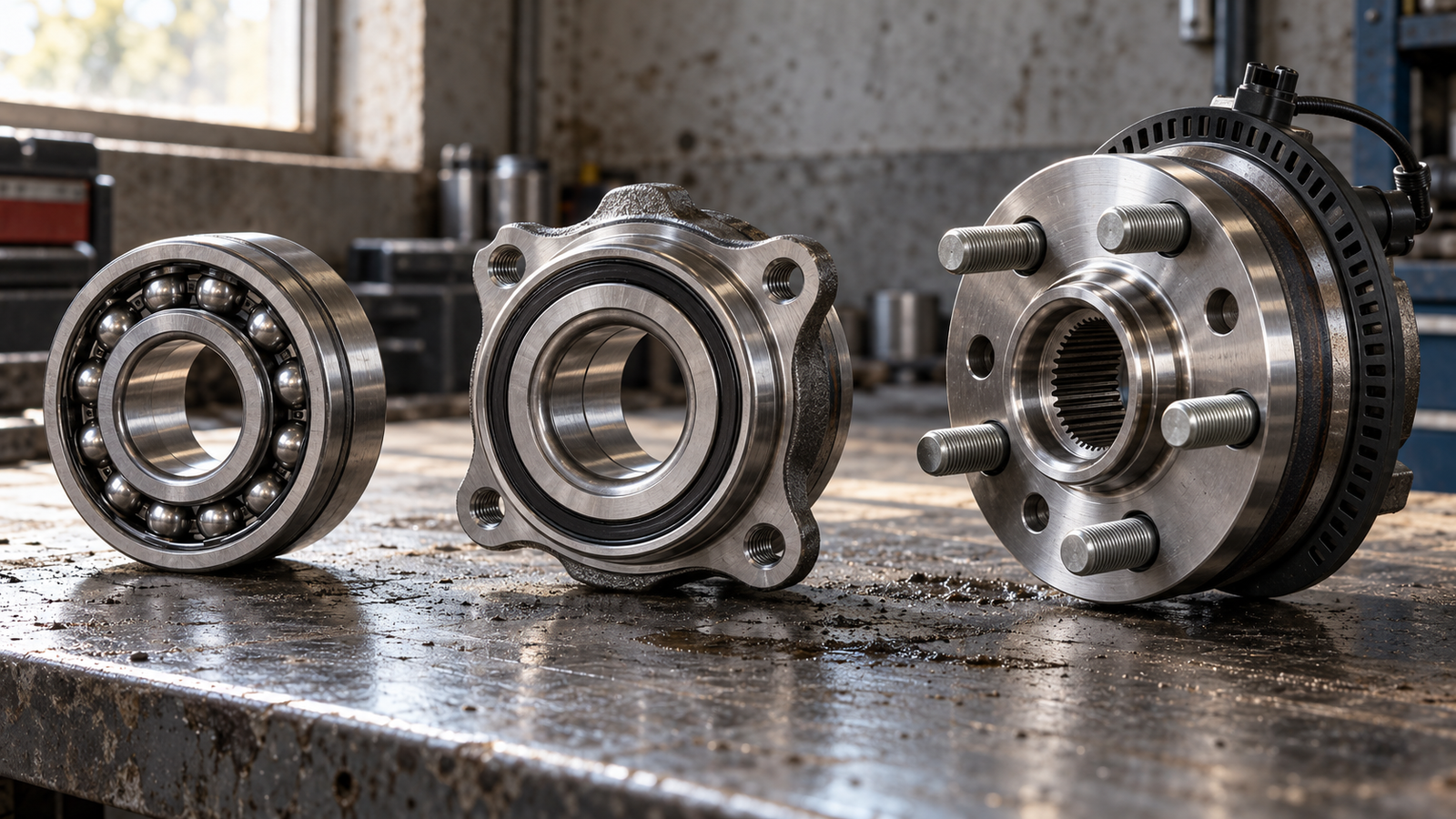
| Generation 1 | Double row ball or roller bearing only; hub and flange are separate parts | Pressed into the knuckle or onto the spindle, secured by axle nut | No encoder in the bearing; sensor reads a tone ring fitted elsewhere | Lowest part complexity, longest fitting sequence, several parts to stock per corner |
| Generation 2 | Bearing plus outer flange carrying brake disc and wheel | Bolted to the knuckle with three or four bolts | Encoder ring often integrated into the seal | Shorter fitting time; flange face runout and bolt torque become critical |
| Generation 3 | Bearing plus outer flange and inner splined flange driving the wheel | Bolted or pressed to the knuckle, driveshaft spline through the centre | Integrated magnetic encoder with a defined air gap | Pre-set preload; axle nut torque is mandatory; sensor gap cannot be adjusted |
| Hub unit assembly | Generation 3 bearing supplied with housing or knuckle as one module | Bolted as a complete module | Encoder and connector position fixed by the housing | One operation per corner, geometry built in, higher unit value per part number |
Which generation should you quote
Quote the generation the vehicle was built with; do not substitute across generations. A generation 1 corner cannot accept a generation 2 unit without changing the knuckle, brake interface and sensor arrangement, and a generation 3 unit depends on a spline and axle nut that a generation 1 corner does not provide. Downgrading is equally unsafe because the sensor signal path disappears.
For mixed fleets the practical answer is to group part numbers by corner architecture rather than by model name, then map each platform onto that grouping. A bearing and hub assembly selection guide is useful here because it walks through the same decision from the load side rather than the catalogue side.
Which Bearing Type Matches Which Position and Load?
Rolling element geometry follows load direction: tapered roller bearings carry combined radial and axial load at the wheel, while cylindrical roller bearings are chosen for high radial capacity where axial location is handled by another component.
Tapered roller versus cylindrical roller bearings
Both types appear in vehicle running gear, but they are not interchangeable. The comparison below covers the attributes that decide the choice.
| Attribute | Tapered roller bearing | Cylindrical roller bearing |
|---|---|---|
| Load direction | Combined radial and axial load; axial capacity depends on contact angle | Predominantly radial; negligible axial capacity in the basic design |
| Stiffness | High, especially in a paired or adjusted arrangement | High radial stiffness, lower axial location stiffness |
| Typical position | Non-driven wheel hubs, commercial vehicle wheel ends, differential and gearbox shafts | Gearbox and transmission shafts, high radial load supports, some wheel end variants |
| Adjustment | Requires bearing play or preload setting where the design is adjustable | Usually located axially by a shoulder, snap ring or adjacent bearing |
| Speed behaviour | Good, with correct lubrication and setting | Good radial performance, sensitive to misalignment |
| What to confirm | Contact angle, cup and cone matching, setting procedure | Radial clearance class, axial location method, cage type |
In markets where light trucks and vans share the road with passenger cars, both families appear in one importer’s catalogue. A separate overview of commercial vehicle hub bearing applications explains the heavier wheel-end arrangements that use tapered rollers and how they differ from passenger car units.
Tensioner and tensioner pulley bearings
A tensioner bearing is a sealed deep groove ball bearing mounted eccentrically in a pulley or arm so it can take up slack in the accessory drive belt. It carries belt tension as a steady radial load plus the dynamic load from belt runout, and it rotates continuously at speeds set by pulley diameter rather than engine speed.
The load is modest but the duty cycle is severe: heat from the engine bay, dust, and constant rotation. Failures are usually traced to seal degradation and grease loss rather than to raceway fatigue, and misalignment of the belt run is a common external cause. When replacing a tensioner assembly, confirm the pulley diameter, offset and arm geometry against the drawing and sample, since visually similar pulleys differ in offset.
CV joint and driveshaft assemblies
A constant velocity joint transmits torque through an angle at constant rotational speed; the fixed ball joint at the wheel end allows steering angle, and the plunging joint at the gearbox end absorbs suspension travel. Both are grease-filled and boot-sealed, and both are sensitive to boot integrity rather than to bearing clearance.
The connection to the hub bearing is mechanical and easy to underestimate. The outboard joint spline engages the hub spline, and the axle nut clamps the joint face against the bearing inner ring, generating the axial force that holds a generation 3 unit together. Under-torque here shows up later as bearing noise or spline fretting, so the nut torque and the use of a new nut belong in the fitting instructions, confirmed by drawing and sample.
Clutch release bearings
A clutch release bearing is a thrust-loaded angular contact bearing that converts fork or hydraulic actuator movement into a force on the diaphragm spring while rotating with it. Constant-contact hydraulic release bearings run continuously against the spring and therefore depend on a controlled preload and a stable seal, while conventional designs contact only during pedal travel.
Because the load is axial and the speed follows engine speed, the critical parameters are contact geometry, grease retention and guide tube fit. A release bearing that howls within a short period usually indicates misalignment on the guide tube or a worn fork rather than a defective bearing, which is an application finding rather than a quality finding.
How Do Material, Heat Treatment, Clearance and Sealing Change the Application?

Two bearings with identical dimensions can behave differently in the same application because steel grade, heat treatment, clearance class and seal design alter fatigue life, stiffness and contamination tolerance.
Bearing steel and heat treatment
Automotive hub bearings are normally made from through-hardening bearing steel of the 100Cr6 type, with controlled inclusion content and a specified hardness after hardening and tempering. Flanged units and parts subject to impact often use case-hardening grades so the surface resists fatigue while the core retains toughness, and some flange geometries are induction hardened locally.
What matters to a buyer is not the grade name alone but the process control behind it: hardening temperature, tempering, retained austenite level and dimensional stability after heat treatment. These are the points covered in more detail in this note on bearing steel quality and heat treatment, and they are the questions to put to a supplier during a technical review.
Precision grade and internal clearance
Precision grade describes dimensional and running accuracy tolerances, not load capacity: a higher grade tightens tolerances on bore, outside diameter, runout and width variation, and does not make the bearing stronger. For hub units the relevant output is flange runout and the consistency of the preload set at assembly, because those control brake judder and bearing noise.
Internal clearance follows the same logic. Where a design is adjustable, the workshop sets play or preload; where the unit is sealed and pre-set, the clearance is fixed by the manufacturer and the buyer verifies end play and torque-to-rotate as acceptance criteria. Specify the acceptance value in the purchase document rather than assuming the supplier applies the same limit.
Sealing and lubrication
Sealing decides service life in dusty, wet or high-pressure-washing markets more often than steel quality does. A typical hub unit uses a multi-lip seal with a primary lip, a secondary dust lip and a grease retainer, and generation 2 and 3 units often integrate the magnetic encoder into the seal body, which makes seal geometry and sensor function one component.
Lubrication is a measured fill of a specified grease, sealed for life, with no routine top-up. Consequences for the buyer are simple: never open a sealed unit, never wash a bearing with solvent, and never fit a unit whose seal lip has been deformed in storage. Where a market combines fine dust with monsoon or coastal humidity, the seal and grease specification is the first item to raise, not the last.
How Do You Read a Hub Bearing Drawing Before Approving a Sample?
A drawing is only usable when it carries the parameters that decide fit, because two units that agree on bore, outside diameter and width can still fail to fit or to signal correctly.
The parameters that decide fit
Read the drawing for bore, outside diameter and width first, then for everything that touches the vehicle: flange diameter and thickness, bolt circle diameter, bolt thread and hole count, hub pilot diameter, flange offset, spline count and major diameter, axle nut thread, brake disc locating diameter, and the ABS encoder type with its air gap and connector orientation.
Then check the non-fitting data that determines behaviour: raceway geometry and contact angle, steel and heat treatment specification, grease type and fill, seal construction, marking content and packaging. Anything missing from the drawing becomes a question, not an assumption. Where OE numbers are being mapped across applications, this explanation of an OE cross-reference and fitment file shows how to keep the mapping traceable to a drawing revision.
A seven-step sample approval sequence
Approval works best as a fixed sequence, so that dimensional, functional and documentation checks are not mixed.
- Match the request to a drawing revision and record the revision number on the approval sheet.
- Measure the dimensional envelope: bore, outside diameter, width, flange diameter, offset and bolt circle.
- Verify the ABS interface: encoder type, pole count where applicable, air gap and connector orientation, confirmed by drawing and sample.
- Check the spline and thread: spline count and fit, axle nut thread, and thread condition on the sample.
- Trial-fit the sample on a representative knuckle or hub carrier and confirm that no interference exists through full suspension and steering travel.
- Measure torque-to-rotate and end play, and record the values against the agreed acceptance limits.
- Inspect marking, packaging and label data, then release the sample as the reference for future shipments, retained in a sealed state.
Which Failure Modes Show the Application, Not the Part, Is Wrong?
Most hub bearing failures that return to an importer are application failures, and the wear pattern identifies which application condition caused them.
Reading the wear pattern
Failures cluster into a small number of recognisable patterns. The table below maps each pattern to its usual cause and to what it says about the fitment.
| Pattern | Appearance | Usual cause | What it indicates |
|---|---|---|---|
| Localised raceway spalling | Flaking concentrated in one loaded zone | Misalignment, bent knuckle face, incorrect seating | Fitting or mating part geometry, not bearing material |
| Bore fretting | Grey or reddish staining and micro-welding on the bore or spline | Loose fit, under-torqued axle nut, reused nut | Installation torque and clamping |
| Seal lip wear with grease loss | Hardened or torn lip, grease expelled, dirt ingress | Pressure washing, abrasive dust, damaged seal in storage | Environment and handling |
| Encoder damage | Scuffed or cracked encoder ring, intermittent ABS signal | Installation impact, wrong air gap, debris | Fitting procedure at the sensor interface |
| Brinelling | Indentations spaced at roller pitch | Impact load, or long storage with vibration | Road conditions or warehouse handling |
| Overheating | Blue or brown discoloration, hardened grease | Under-torque, brake heat, incorrect grease | Clamping force or thermal environment |
Noise and vibration as application evidence
Noise is a symptom with a location, so record where and when it appears before removing anything. A hum that rises with road speed and changes on a curve usually points to a wheel end; a noise that changes with engine speed points to the accessory drive or transmission. Tyre and brake sources must be excluded first, because they mimic bearing noise convincingly.
The diagnostic sequence for confirming a wheel end fault is set out in this guide to hub bearing noise diagnosis, and a shorter workshop version appears in this note on how to tell a wheel hub bearing is failing. Both end at the same conclusion: confirm the source before the corner is dismantled.
How Should Multi Vehicle Hub Bearings Be Installed and Received?

Installation and incoming inspection protect the two things a supplier cannot control after despatch: clamping force at the axle nut and contamination during storage.
Installation and replacement points
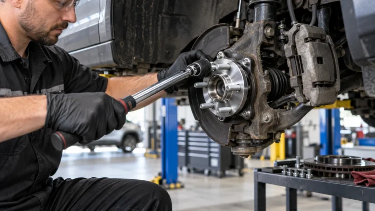
Press or drive on the ring that is designed to take the force, never on the flange, cage or encoder ring. Clean the knuckle bore and remove burrs and old locking compound, since a bore that is out of round transfers directly into the outer ring. Use a new axle nut where the design specifies one, apply the stated torque without impact tools, and check the ABS signal after fitting rather than after the first test drive.
For generation 3 units the axle nut torque is a functional setting, not a finishing step: it establishes the clamping force that holds the joint face against the inner ring. Reusing a distorted nut or stopping short of the torque figure produces a bearing that fails for reasons that never appear in the bearing itself. Pair bearing replacement with a check of the mating hub, knuckle and driveshaft spline, because a worn mating surface will destroy a new unit quickly.
Incoming inspection at the warehouse
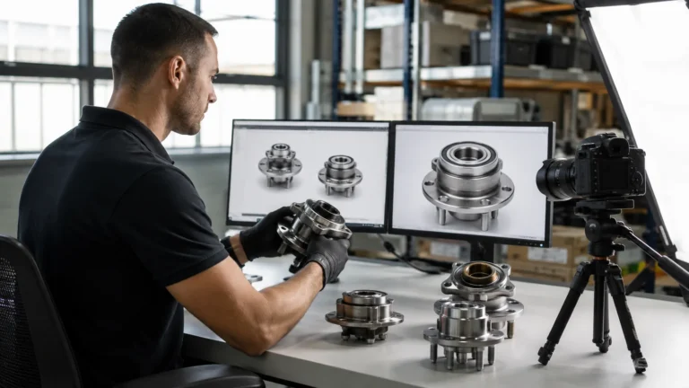
Incoming inspection should be short, repeatable and documented. Check carton condition and label data against the purchase order, confirm that the marking on the unit matches the part number, verify that seals and encoder rings are undamaged, and rotate a sample by hand to feel for roughness or axial looseness. Spot-check key dimensions with a micrometer or caliper against the approved drawing revision.
Keep the approved sample sealed and use it as the reference for later deliveries, including packaging artwork where private label is involved. The structure of a written enquiry is covered in this RFQ checklist for wheel hub bearings, which pairs well with a documented goods-in routine so that expectations and verification match.
Frequently Asked Questions About Multi Vehicle Hub Bearing Applications
These are the questions that come up most often when a single bearing number is proposed for several vehicle models.
Can one hub bearing really cover several vehicle models?
Yes, when the vehicles share a corner architecture: the same envelope dimensions, flange pattern, spline and ABS interface. Platform sharing makes this common across brands and model years. Coverage is only valid per application, however, so each model must be confirmed against the drawing and an approved sample rather than assumed from a shared dimension.
What is the difference between a wheel hub bearing and a hub assembly?
A wheel hub bearing is the bearing element itself, while a hub assembly adds the flange, and often the housing, encoder and mounting hardware as one unit. Assemblies reduce fitting steps and fix the geometry at the factory; separate bearings cost less per part but require more workshop operations and more care over seating and torque.
Does a higher precision grade make a hub bearing last longer?
Not directly. Precision grade controls tolerances on bore, outside diameter, runout and width variation, which affects noise, brake judder and fitting consistency. Fatigue life depends more on steel cleanliness, heat treatment, preload setting, sealing and lubrication. Grade and life are separate attributes and should be specified separately.
How do I confirm an OE number before ordering?
Use the OE number as a search key, then confirm the part against the drawing, the sample and the vehicle corner data: dimensions, flange offset, spline, encoder type and connector. Numbers get superseded and reused across applications, so a match on the number alone is not confirmation. Where supersession chains exist, track them explicitly.