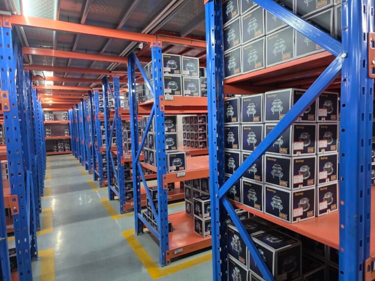

3501140-BU02 Wheel Hub Bearing Unit: What It Is and How to Check
3501140-BU02 is an OE-style reference for a wheel hub bearing unit: a pre-assembled, pre-greased and sealed hub bearing that carries wheel load, locates the brake disc and often holds the ABS encoder. It belongs to the HJDP wheel hub bearing range made by Jinan Huayuan Auto Bearing Co., Ltd. and sold through jnhjdp.com. The number identifies a family of designs rather than one fixed geometry, so bore, flange bolt circle, offset, seal type and ABS interface must be confirmed on the drawing and on an approved sample before ordering.
What Is 3501140-BU02 and Where Does It Sit on a Vehicle?
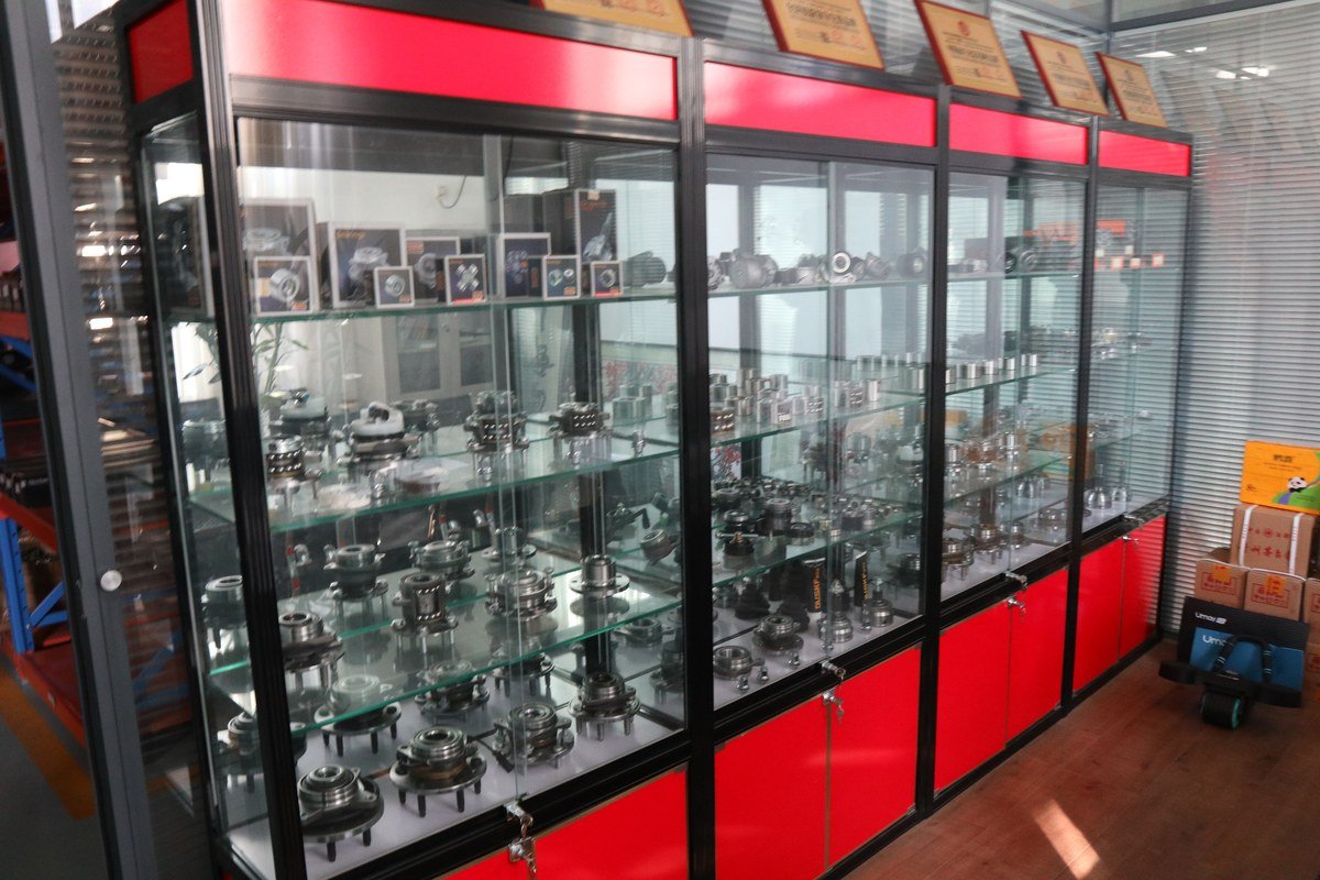
The part is a unitised wheel bearing: bearing, flange, seals, grease and encoder leave the factory as one assembly that is replaced as a whole. Unlike a loose bearing, it has no separate cup and cone to adjust and no grease point to service; internal clearance is set during assembly and stays fixed for the life of the part.
Its job is to do three things at once. It transfers the vertical load of the vehicle from the suspension to the wheel, it lets the wheel rotate with low friction under that load, and it holds the brake disc or drum in a fixed radial and axial position so that runout, brake judder and uneven pad wear stay within tolerance. On a driven axle it also passes drive torque through the splined or bolted interface. The HJDP wheel hub bearings range covers first, second and third generation units on this principle.
How Can You Tell a Hub Unit From a Loose Wheel Bearing?
A hub unit always carries its own mounting interface, while a loose bearing is only the rolling element set. If the part has a flange with wheel studs, a bolt pattern for the knuckle, or both, it is a unit. If it arrives as a cup and cone, a sealed cartridge or a bare ring, it is a bearing that presses into a separate hub or knuckle. The distinction matters when ordering, because a unit is not interchangeable with a bearing-plus-hub combination even when bore and outer diameter appear to match.
Which Positions on a Vehicle Use This Kind of Unit?
Flanged hub units sit on the front knuckle of front-wheel-drive cars and light vans, and on the rear axle of both driven and non-driven layouts. Load direction differs by position. A front unit on a driven axle sees combined radial load from vehicle weight plus axial load from cornering and drive torque; a rear unit on a non-driven axle sees mostly radial load, but kerb strikes and potholes add short, very high shock loads that a static load figure does not describe. Truck and trailer hubs more often use paired tapered roller bearings in a serviceable hub, which is a different service model and a different spare-parts logic.
Which Generation — Gen 1, Gen 2 or Gen 3 — Does 3501140-BU02 Correspond To?
Generation describes where the flanges sit on the unit, not the quality of the bearing inside it. A Gen 1 unit has no flange and is pressed into the knuckle; a Gen 2 unit has an outer-ring flange that bolts to the knuckle or axle carrier; a Gen 3 unit adds a wheel-mounting flange to the inner ring, so the unit becomes the hub itself. Which of the three a given reference refers to has to be read from the drawing, because suppliers have applied the same style of reference to more than one arrangement over time.
| Generation | Flange arrangement | How it mounts | ABS interface | Buyer notes |
|---|---|---|---|---|
| Gen 1 | No flange on either ring; double-row angular contact ball or tapered roller set | Pressed into knuckle and onto spindle; needs a press and correct support | Encoder ring built into the seal on some versions | Lowest cost, but installation errors are the most common cause of early failure |
| Gen 2 | Flange on the outer ring only | Bolted to knuckle or axle carrier; inner rings locate on the spindle | Encoder in seal, sensor mounted on the knuckle | Usually no press needed; sensor gap and flange face cleanliness decide the result |
| Gen 3 | Flange on the outer ring plus wheel-mounting flange on the inner ring | Bolts to knuckle; wheel bolts directly to the hub flange | Encoder ring integrated in the seal, sensor bore in the housing | Complete hub: verify bolt circle, offset and sensor style before ordering |
Why Does the Generation Change the Replacement Job?
Because the tooling and the failure risk change with it. A Gen 1 unit needs a press, support on the designated ring only, and a clean bore; pressing on the outer ring or driving the unit in with a hammer brinells the raceways before the vehicle moves a metre. Gen 2 and Gen 3 units are usually bolted, so the critical points move to flange face cleanliness, bolt torque and sensor gap. A workshop that receives the wrong generation loses a lift for the day even when the dimensions look close, which is why the generation should be stated on the quotation, not inferred from a catalogue title.
Why Is a Catalogue Number Not a Drawing?
A catalogue number tells you which family of parts is being discussed; a drawing tells you which part you will actually receive. Aftermarket catalogues cross-reference numbers between original equipment and several aftermarket producers, and those cross-references often group parts that share an application but differ in seal design, encoder type or flange offset. The reliable order of confirmation is drawing first, sample second, catalogue third. Where a reference such as 3501140-BU02 is quoted, treat vehicle lists as a hint and the drawing as the specification, with fitment subject to drawing and sample confirmation.
Which Bearing Type Handles Which Load — Tapered, Cylindrical or Angular Contact?

Load direction, not vehicle size, decides the bearing type inside a hub. Radial load comes from the weight of the vehicle and axial load from cornering and drive forces, and the combination decides whether a ball or roller bearing is appropriate. The table below compares the types that appear in wheel-end and driveline positions.
| Bearing type | Load direction | Stiffness and speed | Typical position | What buyers should know |
|---|---|---|---|---|
| Double-row angular contact ball | Radial plus axial in both directions | High stiffness, low friction, good speed capability | Passenger-car hub units, Gen 1 to Gen 3 | Clearance preset and sealed for life; no adjustment in service |
| Tapered roller, single or paired | Radial plus axial in one direction per row | Very high combined capacity, lower speed limit | Truck, trailer and non-driven hubs; older rear-wheel-drive front ends | Requires end play or preload setting; often a serviceable design |
| Cylindrical roller (NU, N, NJ) | High radial, little or no axial | High radial stiffness, separable | Gearbox shafts, industrial hubs, some driveline supports | NU, N or NJ choice depends on which ring locates the shaft axially |
| Deep groove ball | Radial plus light axial | Low friction, high speed | Auxiliary positions and tensioner pulleys | Not a substitute for a hub unit, regardless of matching bore |
Where Do Tensioner and CV Joint Bearings Fit?
They solve different problems in the same driveline. A tensioner pulley bearing is a sealed ball bearing running at high speed under belt tension, so its limiting factor is grease life and seal friction rather than load capacity. A constant velocity joint transmits torque through a varying angle: ball-type joints are used at the wheel end of a driveshaft, tripod joints at the inboard end, and both depend on the boot and its clamps to keep grease in and grit out. HJDP supplies tensioner and tensioner pulley bearings and CV joint assemblies as separate ranges, specified from the pulley or shaft interface rather than from hub dimensions, so the ordering data is not interchangeable with a hub unit.
Which Specification Suits Dust, Water and Heat?
The operating environment, not the catalogue page, sets the seal and grease choice. A unit running behind a brake disc on a front axle lives with radiant heat and brake dust; a rear unit on a light truck in a dusty region sees fine abrasive dust and occasional water crossings. For those conditions the priorities are a multi-lip or cassette seal, an HNBR or FKM lip where temperatures run high, and a grease with enough base oil viscosity and oxidation stability for the duty. Importers working in hot, dusty or coastal markets should request the seal and grease specification in writing instead of assuming it from the part number.
How Do Steel, Heat Treatment, Clearance and Sealing Decide Service Life?
Two units can share identical envelope dimensions and still differ several-fold in life, because life is set by steel cleanliness, heat treatment, seal design and grease fill rather than by outside diameter. Dimensions get a part onto the vehicle; metallurgy and sealing decide how long it stays there.
Which Steel and Heat Treatment Are Used in Hub Bearings?
Raceways and rolling elements are normally made from through-hardening bearing steel such as GCr15 (100Cr6), hardened and tempered to roughly 58 to 62 HRC with a fine-grained martensitic structure and controlled retained austenite. Shock-loaded and heavy-duty parts sometimes use case-carburised steel, which keeps a tough core under a hard surface. Flanges are frequently induction hardened at stud seats or splines, and cages are glass-fibre reinforced polyamide for light units or steel where temperatures and loads are higher. Steel cleanliness, meaning oxide inclusion content, is the variable most often invisible on a quotation and most closely linked to fatigue life.
How Are Precision Grade, Runout and Clearance Specified?
Hub units are commonly specified to ISO P6 or P5 boundary tolerances, but the figure that matters most in service is flange runout, not the tolerance class of the bearing alone. Lateral runout of the wheel-mounting flange and radial runout of the pilot diameter are stated on the drawing, often in the order of a few hundredths of a millimetre, and excess runout appears as brake judder and uneven pad wear. Internal clearance in a hub unit is set at assembly and cannot be adjusted on the vehicle, so a unit that arrives with detectable axial play is already outside specification. Tapered roller hubs are the exception: they are set to a stated end play or preload during installation, and both excessive play and excessive preload shorten life.
How Do Seals, Encoder Rings and Grease Work Together?
Sealing is a system, not one lip. A typical hub unit uses a cassette or labyrinth seal with an elastomer lip running on a ground surface, grease with a lithium-complex or polyurea thickener filled to roughly a quarter to two-fifths of the free space, and a magnetic encoder ring bonded into the seal or fitted to the inner ring. The encoder is part of the sealing package: damaged or contaminated with metallic debris, it degrades the ABS signal even when the bearing itself is sound. Units sealed for life should not be topped up; adding an incompatible grease softens the existing thickener and can cause leakage past the lip.
How Do You Read the Drawing and Approve a Sample for 3501140-BU02?
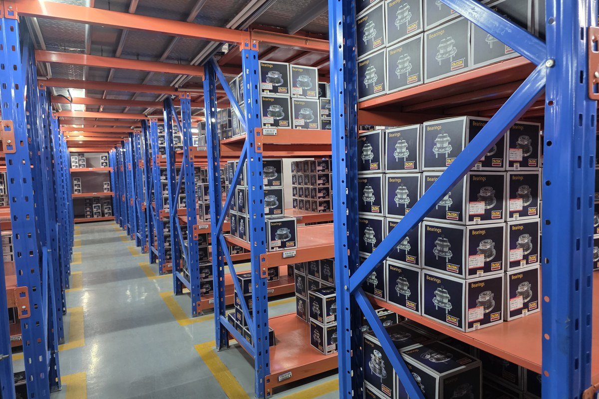
The drawing is the only document that fully defines the part, so confirmation should follow it step by step instead of starting from a vehicle list. The sequence below catches most mismatches before an order is placed.
- Request the drawing, not only the catalogue page, and check that it carries a revision number and date.
- Measure the boundary dimensions — bore, outer diameter, width or overall height — and compare them with the drawing rather than with the old part alone.
- Confirm the flange geometry: bolt circle diameter, number of holes or studs, thread size, hub pilot diameter and offset from the mounting face.
- Confirm the ABS interface: whether an encoder ring is fitted, its position relative to the sensor bore, and the sensor style the vehicle uses.
- Check seal type, grease specification and marking requirements, since these are the items most often changed between revisions.
- Approve a physical sample: rotate it by hand for roughness, measure axial and radial play with a dial gauge, inspect the seal lips and encoder surface, and verify the marking.
- Test fit on a knuckle or hub where possible, then record the approved sample and its revision as the reference for later shipments.
- Agree packaging and private-label marking in writing at the same time, so the approved sample and the shipping carton describe the same part.
Which Drawing Parameters Must Match Exactly?
| Parameter | Why it decides fit | How to verify |
|---|---|---|
| Bore and outer diameter | Press fit and housing location | Micrometer or bore gauge, three positions |
| Width or overall height, and offset | Brake disc and caliper position | Height gauge against the drawing |
| Flange bolt circle, stud count, thread | Whether the wheel bolts on at all | Caliper across studs, thread gauge |
| Hub pilot diameter and chamfer | Wheel centring, vibration at speed | Caliper plus visual check of the lead-in |
| ABS interface and sensor position | Signal quality and warning lamps | Inspect encoder ring and sensor bore against drawing |
| Seal and grease specification | Water, dust and heat resistance | Visual check plus specification on the drawing |
What Do the Common Failure Modes Tell You About the Cause?
Most hub unit failures can be identified from the symptom before the part is removed, and the pattern usually separates a bearing fault, a sealing fault and an installation fault. Reading the symptom correctly is what stops the replacement part from failing the same way.
| Symptom | Likely mechanism | What to check |
|---|---|---|
| Hum or growl that rises with speed and changes when turning | Raceway fatigue and spalling | Wheel play at twelve and six o clock, grease condition |
| Visible play or wheel wobble | Loose axle nut, worn seat, incorrect press fit | Nut torque history, seat and bore condition |
| Grease weeping at the seal, brown rust staining | Seal lip damage and water ingress | Seal lips, boot condition, storage history |
| ABS warning lamp with no bearing noise | Damaged or contaminated encoder ring | Fault code, encoder surface, metal debris |
| Discoloured housing, burnt grease smell | Overheating from brake drag or excess preload | Brake drag test, correct part and installation depth |
One pattern deserves separate mention: false brinelling. A vehicle or a stored part that stands still under vibration for months can develop shallow flats in the raceways, and the unit then growls from the first kilometre with almost no mileage on it. That is a storage and transport issue rather than a manufacturing defect, and it is one reason goods-in inspection and stock rotation matter for importers holding large quantities.
What Should Be Checked at Goods-In and During Installation?
Two short checklists cover most of the risk: what arrives in the carton, and how the unit is fitted. Both are cheap to run and both catch problems that are expensive later.
Goods-In Checks
- Compare the marking on the unit and the carton with the approved drawing revision, not only with the order line.
- Spot-check bore, outer diameter and overall height with a micrometer and height gauge on samples from each batch.
- Rotate each sampled unit by hand: it should turn smoothly with light drag and no gritty or clicking feel.
- Inspect seal lips for cuts or distortion, and the encoder ring surface for scratches, adhesive failure or metal particles.
- Check rust preventive coverage and packaging integrity, especially after sea freight in humid conditions.
Installation Points That Decide Life
Clean the knuckle bore and spindle until they are free of old threadlocker, rust and burrs, and never pull a unit into place with its mounting bolts, which loads the flange unevenly. Press only on the ring the drawing designates, with a driver that covers the full ring face, and fit a new axle nut where a single-use nut is specified, torqued to the vehicle manufacturer figure and then staked. Check brake disc runout after assembly and confirm the sensor gap where an ABS sensor is involved. A short road test with the wheel raised, listening for speed-related noise while turning left and right, catches most fitting errors before the vehicle leaves the workshop. For complete hub and knuckle assemblies, the same rules apply to the wheel hub unit assemblies, and paired tapered designs follow the same setting logic described for tapered roller bearings.
Frequently Asked Questions About 3501140-BU02
Is 3501140-BU02 a bearing or a complete hub assembly?
It is referenced as a wheel hub bearing unit, which means the bearing, flange, seals and grease are supplied as one assembly. Whether the specific drawing includes a wheel-mounting flange and an encoder ring has to be read from that drawing. It is not a loose cup-and-cone set, and it is not a bare bearing pressed into a separate hub.
Can I order from the number alone without approving a sample?
The number narrows the search but does not define the part. Two suppliers can list the same reference with different seal designs, encoder types or flange offsets, and the difference only appears at installation. Approving a sample against the drawing, and keeping it as the reference for later shipments, is the cheaper route for importers and workshop chains alike.
What should I compare first when cross-referencing an equivalent?
Start with the flange: bolt circle, stud count and thread, pilot diameter and offset. These decide whether the part bolts on at all, and they are easy to measure. Bore, outer diameter and width come next, then the ABS interface and seal type. Vehicle lists in a catalogue are the last check, not the first, because they group parts that are close but not identical.
How can I tell whether wheel bearing noise comes from the front or the rear?
Load the suspect bearing and listen for a change. On a road test, a worn front hub usually becomes louder or quieter as the vehicle turns, because cornering transfers weight from one side to the other; a rear unit changes less with steering and more with speed. Confirming with the wheel raised, and checking play at twelve and six o clock, separates bearing noise from tyre and brake noise.