What Is 154000233aa? CV Axle Assembly Structure and Fit Checks
154000233aa is the reference number used on jnhjdp.com for a right-hand CV axle assembly — a constant velocity driveshaft — listed for the Chery Arrizo 8 on the M1E platform and supplied under the HJDP brand. The unit carries torque from the gearbox to the right front wheel while the wheel steers and the suspension moves. Fitment should be confirmed by measurement and by drawing and sample comparison rather than by model name alone, because shaft length, spline counts, joint diameters and ABS ring type can differ between platform variants.
What Is 154000233aa and What Does a CV Axle Assembly Do?
A CV axle assembly is a complete driveshaft that transmits torque to one driven wheel at constant rotational speed, whatever the steering angle or suspension position. Constant velocity is the defining property: a simple cardan joint speeds up and slows down twice per revolution as its angle increases, which appears as vibration and cyclic loading, whereas a constant velocity joint keeps input and output speed equal so a front wheel can steer and drive at the same time.
The part is a service assembly, not a bag of loose components. Workshops replace the whole unit — outer joint, inner joint, shaft, both boots, grease and retaining hardware — instead of rebuilding joints on the bench. That keeps geometry and grease fill controlled and removes the clamp-and-grease work that causes most premature failures in rebuilds.
What three jobs does the assembly perform?
- Torque transfer at constant velocity. The outer joint delivers drive to the hub at steering angles that commonly reach 40 degrees or more at full lock.
- Length compensation. As the suspension compresses and extends, the distance between gearbox and hub changes by tens of millimetres; the inner joint plunges to absorb it instead of stretching the shaft.
- Containment. Boots, clamps and grease retain lubricant and exclude water and grit, while splines and a circlip locate the assembly axially at both ends.
Why is the right side not interchangeable with the left?
Right- and left-hand shafts on the same car are usually different parts. The differential is rarely centred in the engine bay, so the two shafts differ in length, in damper position or presence, and sometimes in whether the long side runs through an intermediate shaft with a support bearing. On 154000233aa the side designation is part of the definition, not a label of convenience.
The consequence is mechanical. A shaft that is too short can draw the inner joint towards the end of its plunge travel at full droop; a shaft that is too long bottoms out the plunge and pushes axial load into the differential bearing and the hub bearing. Both faults appear weeks later and are usually blamed on the part rather than on selection.
Where does it sit in the driveline?
From the gearbox outwards the chain is: differential side oil seal, inner plunging joint, shaft, outer fixed joint, hub spline, wheel bearing, wheel. The inner end is held axially by a circlip inside the differential on most front-wheel-drive transaxles, or by a bolted flange on some designs; the outer end is held by the hub and the axle nut. Because the outer spline drives directly through the hub, wheel bearing condition and axle condition interact, which is why diagnosis should separate the two before parts are ordered.
How Is a CV Axle Assembly Built, Part by Part?
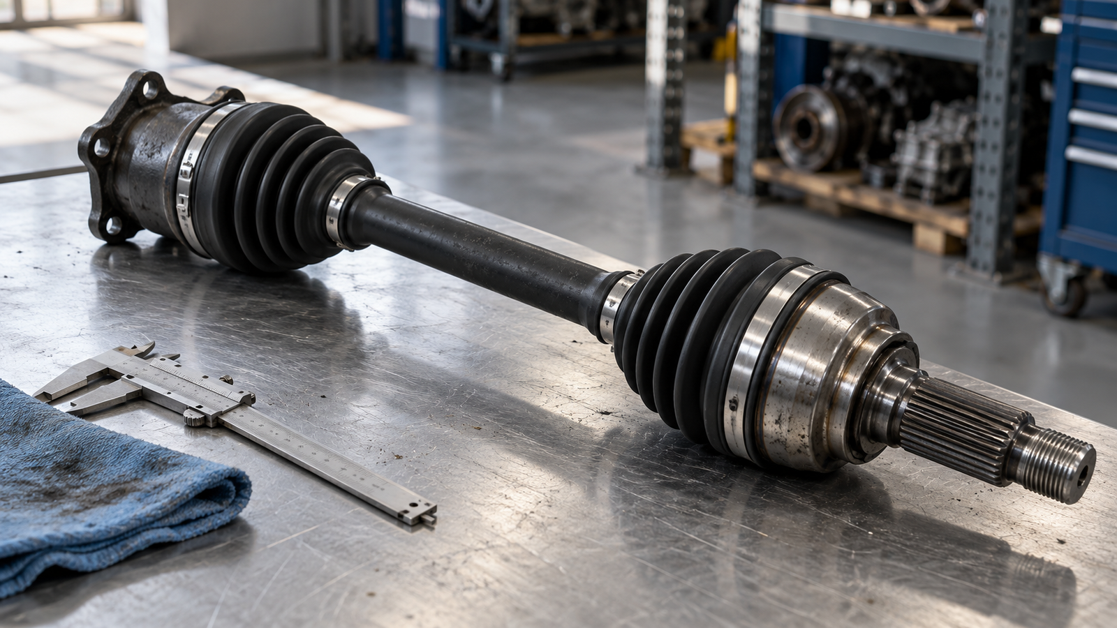
A complete CV axle assembly consists of six functional groups: a fixed outer joint, a plunging inner joint, the shaft, two boots, the grease and clamps, and the wheel-end interface. Each group has its own failure mode and each is a checkpoint when a sample is compared with a drawing.
Outer joint: the fixed, wheel-side end
The outer joint on this class of assembly is normally a Rzeppa ball-and-cage fixed joint: an inner race on the shaft, an outer race in the housing, six balls and a cage that holds them in the bisecting plane. It transmits torque at constant velocity while articulating but does not plunge, because its axial position is fixed by the hub and nut. Balls run in matched grooves, so wear is progressive: clearance opens, the joint begins to click under load at lock, and grease contaminated through a split boot accelerates the process.
Inner joint: the plunging, gearbox-side end
The inner joint absorbs length change and a small angle. Three designs dominate: the tripod joint, with three rollers on a spider running in cylindrical tracks; the double offset joint, a ball type with a plunging cage; and the cross groove joint. Tripod joints are common at the inner position of front-wheel-drive cars because they plunge freely and package compactly. Rollers, needle bearings and track surfaces are the wear points.
Shaft, damper and tuned mass
The shaft is a solid or tubular steel bar with splined or friction-welded ends. Many original designs carry a rubber-and-steel tuned mass damper clamped at a calculated station along the shaft; it suppresses a bending resonance otherwise felt as a boom or drone at a particular road speed. A replacement that lacks a damper the original had, or carries it at the wrong station, can be dimensionally correct and still noisy. Damper presence and position therefore belong on the drawing comparison, not only shaft length.
Boots, grease and clamps
Boots are usually thermoplastic polyester elastomer on modern assemblies, with chloroprene still used on some applications; the thermoplastic type tolerates higher sustained temperatures and suits the greases used with tripod joints. Grease specification matters: a molybdenum-disulphide or polyurea grease chosen for tripod needle bearings is not interchangeable with a plain lithium soap grease, and both over-filling and under-filling shorten life. Clamps are band type, crimped or ear type, and must sit in the boot groove without pinching the pleats.
Materials and heat treatment
Raceways and balls are made from through-hardening or case-hardening bearing steels; shafts are commonly 40Cr, 55# or CF53 steel with induction-hardened splines and, on better designs, shot-peened fillets to raise fatigue resistance. Heat treatment decides whether a joint survives torque peaks at full lock: too shallow a case and the raceway spalls, too hard and it cracks under impact. General practice in this product category is a raceway hardness in the high fifties to low sixties HRC with a defined case depth on carburised parts. The actual material, hardness and case-depth call-outs for 154000233aa are stated on the HJDP drawing and should be read there rather than assumed from another supplier’s sheet.
Which CV Joint Type Is Used Where, and How Do the Designs Differ?
Joint type follows position: a fixed joint sits at the wheel because the wheel steers but does not plunge, and a plunging joint sits at the gearbox because that end must absorb length change. Choosing between plunging designs is a question of angle capability, vibration and package space.
| Joint type | Typical position | Articulation | Plunge | Characteristic wear symptom |
|---|---|---|---|---|
| Rzeppa, ball and cage, fixed | Outer, wheel side | High, commonly 40 to 47 degrees at full lock | None | Rhythmic clicking on full lock under power |
| Tripod, roller and track | Inner, gearbox side | Moderate, roughly 20 to 25 degrees | High | Vibration under acceleration, shudder at low speed on lock |
| Double offset, ball type | Inner, gearbox side | Moderate | Moderate | Rumble and vibration, grease loss at the boot |
| Cross groove | Inner, gearbox side | Moderate to high | Moderate | Noise on overrun, play felt by hand |
Two practical rules follow. A clicking that tracks wheel rotation and worsens on lock is an outer-joint symptom; a vibration that appears under acceleration and fades on the overrun is more often inner-joint plunge wear or shaft imbalance. And joint type cannot be swapped to suit availability, because housing, boot and shaft are designed as a set, so mixing an inner joint from another design changes both plunge range and noise behaviour.
How Do You Confirm That 154000233aa Fits Before You Order?
Fitment is confirmed by measurement and sample comparison, not by the model name in a listing. The model name narrows the search; the dimensions decide the order.
- Read the number on the old part. Record any number etched on the shaft or printed on the original boot and photograph it, then cross-reference that number against the supplier drawing rather than against a marketplace title.
- Measure shaft length in the working position. Measure joint centre to joint centre with the assembly held straight, and record a compressed and an extended figure where possible, since that shows the plunge range the car actually uses.
- Count and measure the outer spline. Count teeth, measure major diameter, note whether the spline is straight or relieved, and record the thread size and pitch at the hub end.
- Count and measure the inner spline. The gearbox-side spline and the circlip groove position must match; a groove in the wrong place will not retain the shaft.
- Measure joint diameters and housing shape. Outer housing diameter, inner housing diameter and boot neck diameters decide whether the unit clears the suspension and the heat shields.
- Identify the ABS interface. Note tooth count and diameter of a toothed ring, or confirm a magnetic encoder ring, and check its axial position on the joint housing.
- Compare a physical sample. Before a bulk order, set the sample beside the removed unit on a flat bench and compare length, spline, damper station, boot shape and retaining hardware. Where any figure is unclear, treat the drawing and the sample as the reference.
| Parameter | How to measure | Why it decides fit |
|---|---|---|
| Shaft length, joint centre to joint centre | Caliper or tape on a straight assembly, compressed and extended | Sets the working plunge range; too short or too long loads the joints |
| Outer spline count and major diameter | Count teeth, measure across the spline outside diameter | Must engage the hub without play or interference |
| Inner spline and circlip groove | Count teeth, measure groove position from the shaft end | Controls axial retention in the differential |
| Joint housing diameters | Measure across the housing at its widest point | Clearance to suspension, subframe and heat shields |
| ABS ring type and tooth count | Count teeth or confirm magnetic ring, measure diameter | Speed signal accuracy and sensor air gap |
| Damper presence and station | Measure from joint centre to damper clamp | Controls resonance and driveshaft boom |
| Axle nut thread and type | Thread gauge; note whether staked, nylon insert or castellated | Torque retention and safe reuse policy |
The catalogue entry for the right CV axle assembly for the Chery Arrizo 8 M1E lists the unit under the HJDP brand. Where a model has more than one platform variant in a market, confirm the number against the drawing and a sample before committing to a container quantity.
How Should a CV Axle Assembly Be Installed?
Correct installation is mostly about not damaging what the part left the factory with: an intact boot, an undistorted circlip and a fully seated spline. Most early-life failures trace back to one of those three.
- Compare the new assembly with the old one on the bench — length, spline, damper station, boot shape — before any dismantling.
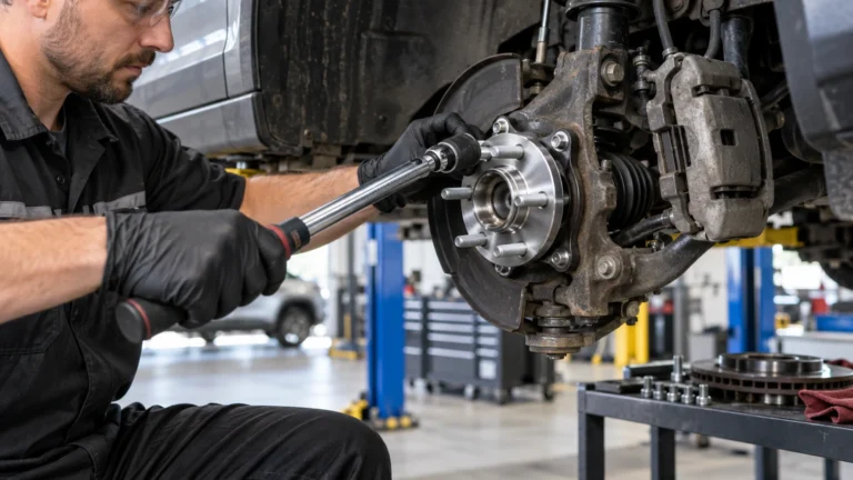
- Loosen the axle nut with the vehicle on the ground and the brakes applied, and use a calibrated wrench for final torque rather than an impact gun.
- Raise and support the vehicle, remove the wheel, and release the outer joint from the hub with a puller rather than hammer blows on the joint face.
- Separate the inner joint from the transaxle carefully; on many transaxles a little oil escapes, so plan for a top-up and inspect the differential seal while access is open.
- Clean the seal bore and hub spline, remove corrosion and old thread-locking residue, and check the seal lip for a wear groove.
- Insert the new assembly horizontally and push until the circlip seats with a distinct click or a firm axial stop; never pull the shaft home by its boot or strike the joint housing.
- Engage the outer spline in the hub, fit a new axle nut where the design specifies a single-use nut, and torque to the vehicle manufacturer figure.
- Check both boots at full droop and full lock for rubbing or twisting, and confirm clamp orientation clears rotating parts.
- Road test at low speed on full lock in both directions, then re-check nut torque and look for grease throw.
Which installation errors cause early failure?
- Reusing a staked or single-use axle nut, which loses preload and allows hub spline fretting.
- Hanging the assembly by the inner joint during fitting, which over-extends the plunge and can dislodge rollers or cage.
- Twisted or pinched boots after clamping, which split within a few thousand kilometres.
- Wrong grease or wrong fill quantity when a boot is replaced instead of the whole assembly.
- Seating the shaft at an angle, which cuts the differential seal lip and creates a leak that is later misread as a joint fault.
What Causes CV Axle Failure, and How Do You Read the Symptoms?
Most CV axle failures begin at the boot, not at the steel: a split or unseated boot lets water and grit into the grease and the joint wears from there. Reading the symptom correctly is what separates a necessary axle replacement from an unnecessary one.
| Symptom | Most likely cause | Quick check | Action |
|---|---|---|---|
| Clicking in step with wheel rotation, louder on full lock under power | Outer joint groove and ball wear | Slow full-lock circle in both directions | Replace the assembly |
| Vibration under acceleration that fades on overrun | Inner joint plunge wear, shaft imbalance or missing damper | Compare vibration in gear against coasting | Check inner joint and damper before ordering |
| Grease sprayed inside the wheel arch | Split boot or unseated clamp | Inspect pleats and clamp seating | Replace the boot early, or the assembly if the joint is already noisy |
| Clunk when drive is taken up | Spline or circlip wear, loose axle nut | Check nut torque and axial play at the joint | Retorque or replace hardware, inspect splines |
| ABS warning after axle work | Tone ring damaged, dirty or of the wrong type | Inspect ring teeth and sensor air gap | Replace the ring or assembly as designed |
How do you separate CV joint noise from wheel bearing noise?
Wheel bearing noise is speed-related and load-sensitive in corners: a droning or humming that changes when weight transfers left or right, and that often continues while coasting in neutral. Outer CV joint noise is torque- and angle-related: it clicks in step with wheel rotation, is loudest on full lock under power and usually quietens when load is released. Because both faults sit at the same corner, and because a worn hub bearing can let the hub move enough to damage a new joint, the wheel bearing should be checked before a replacement axle is fitted.
What Should Importers Check at Goods-In Inspection?
Goods-in inspection should confirm identity, geometry and sealing before stock is booked in, because a mismatch found in the warehouse costs far less than one found on a lift.
- Identity. Part number and side marking on the unit must match the purchase order and the approved sample, and private-label packaging must carry the same reference as the part.
- Geometry. Spot-check shaft length, spline counts and joint diameters against the drawing on a sample from each carton, not only from the first carton opened.
- Boots and clamps. Look for twisted pleats, clamps sitting outside the groove, and grease weeping at the boot neck.
- Splines and threads. Splines should be clean and protected with preservative rather than rusted, and the supplied nut should match the drawing.
- Rotation. Turn the outer joint through its arc by hand: it should move smoothly through the angle range without notching, and the inner joint should plunge without roughness.
- ABS ring. Confirm tooth count and ring type on the sample and check the ring is not deformed from transit.
- Packaging. Cartons should protect boots and joint faces, since a boot crushed in transit becomes a warranty claim in the destination market.
The product listing for 154000233aa is the starting point for reference data, while the drawing and the approved sample remain the acceptance standard. HJDP, the brand of Jinan Huayuan Auto Bearing Co., Ltd., supports drawing and sample confirmation, custom packaging and private-label marking for importers, distributors, parts chains and workshop groups. The same HJDP range covers wheel hub bearings in first, second and third generation designs, hub units, tensioner and idler bearings, clutch release bearings, and automotive tapered and cylindrical roller bearings, so a corner complaint involving hub and driveline can be resolved from one drawing set.
Frequently Asked Questions
Is 154000233aa an OE number or an HJDP catalogue reference?
It is the reference under which the right-hand CV axle assembly for the Chery Arrizo 8 on the M1E platform is listed on jnhjdp.com under the HJDP brand. Whether it cross-references a specific original number, and which production range that number covers, should be confirmed against the drawing and a physical sample rather than assumed from the listing.
Can a right-hand CV axle be fitted to the left side?
Normally no. Left and right shafts differ in length, damper position and sometimes joint design, because the differential is not centred. Fitting the wrong side either over-extends the inner joint at full droop or bottoms out the plunge and loads the differential and hub bearings. Order by side and confirm the reference against the vehicle.
Should the whole assembly be replaced or only the boot?
Replace only the boot when it is caught early: no clicking, no play, clean grease still inside, and the correct grease and clamp available. Once a joint clicks under load, grit has already marked the grooves and a new boot will not restore it, so the assembly becomes the economical repair because its wear surfaces are matched as a set.
Can HJDP supply this assembly with custom packaging or a private label?
Yes. HJDP supports drawing and sample confirmation, custom packaging and private-label marking for importers, wholesalers, parts chains and workshop groups. Reference numbers, marking and carton artwork are agreed before production, and the approved sample defines acceptance for each shipment.