
What Is 154000095aa Right CV Axle Assembly? An HJDP Guide
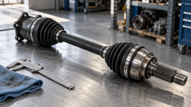
154000095aa is an OE-format part number for a complete right-hand constant-velocity (CV) axle assembly — the drive shaft that carries torque from the transaxle to the right front wheel hub while the wheel steers and the suspension travels. In the HJDP catalogue the number is listed as a right-hand CV axle assembly for Chery Arrizo 5 Plus and Arrizo 5 applications, supplied to the aftermarket under the HJDP brand. Treat the number as an identifier rather than as proof of fitment, because vehicle-specific fitment is subject to drawing and sample confirmation.
What Is 154000095aa?

154000095aa identifies one side of a front-wheel-drive shaft, not a family of interchangeable parts. Importers rarely need to know how the digits were built; they need to know what the number can and cannot tell them, what physically travels in the carton, and why the opposite side is a different item. Those three points decide whether an order will be accepted by the buying channel or returned from it.
How to read a part number in this format
An OE-format number such as 154000095aa works as a search key, not as a specification. Vehicle manufacturers assign numbers for their own catalogue systems, and those numbers can be superseded, can replace an earlier number, or can be shared by trim levels that use mechanically different shafts. The digits do not encode spline count, compressed length, joint housing diameter or ABS tone-ring tooth count, so two assemblies listed under the same number can still differ in hardware. The number’s practical value is that it moves an importer from a vehicle description to a catalogue entry, and from that entry to a drawing. Everything past that step has to be verified physically.
What a complete right-hand CV axle assembly contains
A complete assembly arrives as one serviceable unit: a shaft, two joints, two boots, grease and retaining hardware. Supplying it as a single item removes the risk of mismatched parts at the repair shop, at the cost of a longer and heavier item to store and ship. The table below lists the parts of the assembly and the checks that matter most during incoming inspection.
| Component | Function | What buyers should check |
|---|---|---|
| Outer (wheel-side) joint | Fixed ball-type joint; transmits torque at steering angles up to full lock | Joint type, spline count and diameter, housing diameter, hub retaining method |
| Axle shaft | Carries torque between the two joints | Diameter, surface finish, straightness, position of any damper |
| Inner (transaxle-side) joint | Plunging joint; absorbs changes in shaft length as the suspension moves | Plunge travel, housing interface, spline count, circlip groove width |
| Boots and clamps | Retain grease and keep water, salt and grit out of the joint | Boot material and thickness, clamp type, seating in the groove |
| Grease | Lubricates the joint races and cage | Quantity fitted and whether the joint is supplied pre-greased |
| Circlip | Locks the inner joint into the transaxle side gear | Thickness, spring retention, groove engagement |
| ABS tone ring (where fitted) | Gives the wheel-speed sensor its signal | Presence, position on the shaft or joint, tooth count |
| Damper (where fitted) | Reduces driveline vibration and boom | Presence and position along the shaft against the drawing |
Why a constant-velocity joint rather than a simple universal joint
The wheel-side joint has to transmit torque smoothly at steering angles of 30 degrees or more, which a single Cardan joint cannot do. A universal (Cardan) joint changes output speed twice per revolution as its angle increases, which appears as vibration and as extra load on the joint and boot. A constant-velocity joint is designed to hold output speed constant across the working angle, which is why front-wheel-drive shafts use one at the hub. The transaxle end normally uses a plunging version that also absorbs length change.
Why the right-hand side carries its own part number
Left and right drive shafts are not interchangeable, even when they look similar on a bench. Transaxles sit off-centre in most front-wheel-drive layouts, so the two shafts differ in length, in resting joint angle and often in damper position. A left-hand shaft pushed into the right-hand side can seat on the splines and still load the joint at the wrong angle, which shortens boot and joint life and creates vibration that gets blamed on the wheel. Order, label and store left and right numbers separately.
How Do You Identify a Right-Hand CV Axle Assembly Correctly?
Identify a right-hand CV axle by combining the part number with six physical checks: side, spline count, spline diameter, compressed length, joint housing diameter and ABS tone-ring specification. No single check is strong evidence on its own. The sequence below is written for a warehouse or workshop that still has the old shaft in hand; if the shaft has already been scrapped, work from the vehicle’s own part number and a drawing instead.
- Confirm the number and the side. Read the original number from the old shaft, the vehicle documents or the parts catalogue, and confirm the entry is the right-hand side. Record any supersession the catalogue shows.
- Count and record the splines. Count the teeth on the wheel-side and transaxle-side splines separately, and note whether the ends are chamfered or side-face cut. A one-tooth difference is enough to stop assembly.
- Measure the spline diameters. Use a caliper across the spline major diameter at both ends. Splines with the same count but a different diameter will not seat correctly in the hub flange or the side gear.
- Measure the compressed length. Hold the shaft with the inner joint collapsed against its stop and measure end to end. Compare with the drawing, not with a catalogue photograph.
- Check the joint housings. Record the outer housing diameter, the inner housing diameter, and whether the outer joint is bolted or splined into the hub.
- Check the ABS interface. Note whether a tone ring is fitted, on which joint it sits, and how many teeth it carries. Vehicles on a shared platform can differ here.
- Confirm against a drawing and a sample. Only when the first six steps agree should the number be treated as matched. Fitment remains subject to drawing and sample confirmation.
Which measurements decide whether the shaft fits
Five measurements decide fitment, and all five can be taken with a caliper and a tape. Length decides whether the inner joint can plunge through suspension travel; splines decide whether torque can be transmitted; housing diameters decide clearance to the engine, subframe and brake components. The table below sets out what to measure and why each figure matters.
| Measurement | Why it decides fitment | How to check it |
|---|---|---|
| Compressed overall length | Too long bottoms the inner joint against its stop and loads the transaxle bearing; too short risks disengagement under droop | Collapse the inner joint fully and measure end to end against the drawing |
| Hub-side spline count and major diameter | Sets the interface with the hub flange or hub bearing unit | Count teeth and measure across the splines with a caliper |
| Transaxle-side spline count and major diameter | Sets the interface with the side gear and the retaining circlip | Count teeth, measure, and record the circlip groove width |
| Outer joint housing diameter | Clearance to the knuckle, brake hose bracket and wheel-speed sensor | Caliper across the housing at its widest point |
| Inner joint housing diameter | Clearance to the engine block and subframe at full steering lock | Caliper across the housing; dry fit where a vehicle is available |
| Boot seat diameters and clamp type | Decides whether the boot seals and whether the clamp locks into the groove | Measure the boot seat on the shaft and on the joint housing |
| ABS tone ring presence, position and tooth count | Wrong ring produces a warning lamp or an incorrect speed signal | Visual check plus a tooth count against the drawing |
| Damper presence and position | A missing or wrongly placed damper changes vibration behaviour | Compare position along the shaft with the reference part |
Why two shafts can share one number and still differ
The same number can be listed against several build variants, and those variants do not always use the same hardware. Engine code, transmission type, ABS generation and market specification can each change the shaft while the catalogue entry stays the same. That is why an importer should request a drawing for every batch instead of reusing an old photograph, and why a first-article sample should be approved before a repeat order is placed. Drawing and sample confirmation is therefore treated as part of the order at HJDP, not as an optional extra.
Which Supply Format Should an Importer Choose?
Choose the supply format by what the repair channel can actually install, not by unit cost alone. A workshop with a press and trained technicians can rebuild a joint; a general repair shop or roadside outlet usually cannot, and a joint kit sold into that channel becomes slow-moving stock. Importers who serve both types of buyer commonly carry complete assemblies for fast-moving references and joint kits only where demand justifies them.
| Supply format | What the buyer receives | Where it fits | What to verify |
|---|---|---|---|
| Complete CV axle assembly | Shaft, both joints, boots, grease, circlip | Repair shops without joint-fitting equipment; fast-moving references | All measurements in the checklist; side; tone-ring specification |
| Outer joint kit | Outer joint, boot, grease, clamps, circlip | Workshops equipped to split the shaft and re-boot the inner joint | Spline count and diameter; housing diameter; boot seat |
| Inner joint kit | Plunging joint, boot, grease, clamps | Drivetrain specialists, and vibration repairs traced to the inner joint | Plunge travel; housing interface; circlip thickness |
| Boot and grease kit | Boot, clamps, grease | Preventive maintenance on a joint that is still sound and tight | Boot material and clamp type; joint condition before fitting |
| Shaft only | Bare shaft without joints | Rarely — only where joints are reused with proper shop support | Spline form, length and straightness against the drawing |
How Do Importers Verify Fitment Before Placing an Order?

Fitment verification is a documentation task: the buyer supplies vehicle data and measurements, the supplier returns a drawing, and an approved sample closes the loop. The same process applies to the 154000095aa right-hand axle assembly as to any other reference in the HJDP range. Importers who order directly from a photograph are the ones who discover a spline or tone-ring mismatch after the container has landed.
What information should an enquiry include?
- The OE number exactly as printed, including any suffix or supersession.
- Vehicle make, model, model year band, engine code and transmission type as recorded by the dealer or catalogue.
- Which side of the vehicle the part serves.
- Photographs of the original part from four angles, with a ruler visible in frame.
- Measured figures: spline counts, spline diameters, compressed length, housing diameters, tone-ring tooth count.
- Packaging requirement: neutral packing, HJDP-branded packing, or the buyer’s own label.
- Quantity and the mix of part numbers if several references will ship together.
- A sample of the original part where the number is ambiguous or has been superseded.
What should be checked on a first-article sample?
A first-article sample should be checked against the recorded measurements before any other discussion takes place. Compare spline counts and diameters, compressed length and housing diameters with the drawing; work the outer joint through its steering range and the inner joint through its plunge range to feel for roughness or binding; inspect boot material and clamp seating in the grooves; look for burrs on the spline ends and check the circlip for thickness and groove engagement. Record the results against the part number and keep the approved sample as the reference for later shipments. Where a vehicle is available, a dry fit answers residual doubt faster than any document, and fitment remains subject to drawing and sample confirmation.
What Should Buyers Confirm With HJDP on a Branded Order?
On an HJDP-branded order, three things are confirmed in writing before production: the drawing, the packaging and the marking. HJDP is the own brand of Jinan Huayuan Auto Bearing Co., Ltd., based in Jinan, Shandong, China, and sold through jnhjdp.com. The range covers automotive wheel hub bearings and related running-gear components: first, second and third generation wheel hub bearing units, hub assemblies, tensioner and tensioner pulley bearings, CV joint and constant-velocity axle assemblies, clutch release bearings, and automotive tapered and cylindrical roller bearings. A branded programme adds packaging and documentation on top of that range.
Why does drawing and sample approval come first?
The approved drawing is the reference the whole order is measured against, which is why it is agreed before production starts. It fixes the dimensions, the joint arrangement, the boot and clamp type, the tone-ring specification and the marking. If a dimension changes after approval, the approval restarts, because a change to one dimension usually moves the interface with the hub or the transaxle. Importers should file the signed drawing with the approved sample and quote both on repeat orders.
How do custom packaging and private label work?
Custom packaging and private-label marking are available for importers who sell under their own name rather than under HJDP. A packaging specification should cover box size and material, label content and layout, part-number and barcode format, quantity per carton, carton marking, and pallet configuration. The same document should state which items carry the buyer’s mark and which stay neutral. Agreeing this in writing before production avoids relabelling work at the warehouse and keeps a mixed consignment identifiable on arrival.
Can several part numbers ship in one consignment?
Yes, and most importers combine references so that a slow-moving number does not need its own container. A mixed consignment works when the packaging specification is agreed reference by reference and every carton carries its own label and part number. Buyers usually group by product family — wheel hub bearing units in one set of cartons, CV axle assemblies in another — because the cartons differ in size and because the receiving warehouse stores stock by family. Agree the mix and the marking before production.
Which Symptoms Mean the Axle Must Be Replaced?

Clicking on turns, or a joint that has run without grease, means replacement rather than a repack. A CV joint that has run dry has already lost its race and cage surface finish, and fitting a new boot over it simply moves the failure a few thousand kilometres down the road. The table below maps common complaints to the failure they usually indicate and to the checks that confirm it.
| Symptom | Usual cause | How to confirm | Action |
|---|---|---|---|
| Rhythmic clicking on full lock, worse in one direction | Outer joint wear | Inspect the boot for splits; check joint free play with the shaft removed | Replace the assembly or the outer joint kit |
| Vibration at road speed that changes with throttle position | Inner plunging joint wear, shaft imbalance or a missing damper | Check for grease loss, feel plunge roughness, compare the damper position with the drawing | Replace the assembly |
| Grease thrown onto the inner wing or subframe | Split boot or a clamp that has left its groove | Inspect boot walls and clamp grooves | Boot kit if the joint is still tight; otherwise replace |
| Clunk when drive is engaged | Worn splines, a flattened circlip, or wear in the transaxle side gear | Inspect splines and the circlip groove | Replace the shaft and investigate the transaxle separately |
| ABS or wheel-speed warning | Tone ring damaged, corroded or displaced | Compare the ring with a known-good assembly | Replace the shaft or the ring, depending on design |
| Low-speed wobble or steering shudder | Excessive plunge play or a bent shaft after impact | Dial-test the shaft and check for kerb damage | Replace the assembly |
How Should a Right CV Axle Assembly Be Installed?
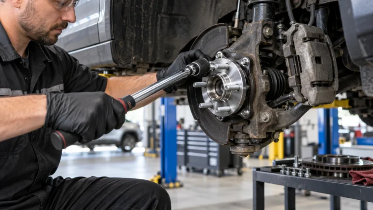
Installation is a sequence question, and most comebacks come from forcing the shaft or reusing single-use hardware. Torque figures and fluid quantities come from the vehicle manufacturer’s workshop data, not from a parts supplier, so they are not reproduced here. What follows is the sequence that keeps a new joint out of trouble.
- Loosen the axle nut while the vehicle is on the ground or with the brakes applied and the wheel fitted, because these nuts are usually tightened to a high value and the hub will spin once the wheel is removed.
- Raise and support the vehicle correctly, then remove the wheel on the affected side.
- Release only what the manufacturer’s procedure requires — typically a track rod end or lower ball joint, sometimes the caliper and disc — and support the knuckle so it does not hang on the brake hose.
- Separate the outer joint from the hub with a proper puller or a drift applied to the joint housing. Never strike the shaft, the boot or the threaded end.
- Support the transaxle side before withdrawing the shaft, and be ready to catch fluid on designs where the seal does not retain it.
- Withdraw the inner joint squarely and remove the circlip. Do not lever on the joint housing against the transaxle casting.
- Fit a new circlip, and replace any seal, dust cover or axle nut the manufacturer lists as single-use.
- Insert the inner joint until the circlip seats, then slide the outer splines into the hub. If they will not enter by hand, stop and recheck spline count and diameter rather than forcing them.
- Reconnect the suspension and brake components and tighten every fastener to the manufacturer’s specified torque.
- Fit a new axle nut and tighten it to the specified torque with the vehicle braked, then check the transaxle fluid level and top up as required.
- Check wheel alignment if any geometry component was released, confirm no warning lamps remain, and road-test through the full steering range in both directions.
What are the most common installation mistakes?
- Reusing the old axle nut on a design where it is a single-use, torque-to-yield item.
- Pulling the shaft into the hub with the nut instead of seating the splines by hand first.
- Hammering the end of the shaft, which damages the joint race behind it.
- Letting the knuckle hang on the brake hose or the ABS harness.
- Fitting a boot kit to a joint that has already run dry.
- Storing or carrying a new shaft on its boot, which deforms the boot before it is installed.
Which Questions Do Buyers Ask Most About 154000095aa?
Is 154000095aa used on both sides of the vehicle?
No. The number identifies the right-hand side, and the left-hand shaft carries a different number because the two shafts differ in length and joint geometry. Supplying the left part for the right side, or the reverse, is a common cause of vibration and early boot failure. Confirm the side on both the invoice and the packing list, and treat fitment as subject to drawing and sample confirmation.
Can a CV axle be matched on spline count alone?
No. Spline count is one of six checks that decide fitment, alongside spline diameter, compressed length, joint housing diameters, ABS tone-ring specification and the retaining method at the hub. Two shafts with an identical spline count can differ in length by enough to bottom out the inner joint. Match every recorded figure against a drawing, then confirm with a sample.
Is a wheel alignment needed after replacing a CV axle?
Only if the replacement disturbed a component that sets the suspension geometry. Many designs allow the shaft to be withdrawn after separating a ball joint or track rod end, and those components shift the alignment when refitted. If the procedure did not release any geometry component, an alignment is not normally required. Follow the manufacturer’s procedure and check alignment wherever geometry was disturbed.
What should an importer send to obtain an accurate quotation?
Send the exact OE number, the vehicle’s make, model, model year band, engine code, transmission type and side, photographs with a ruler in frame, and measured spline counts, diameters, compressed length and tone-ring tooth count. Add the packaging specification, the mix of part numbers if several references are being quoted, and a sample where the number is ambiguous or has been superseded.