

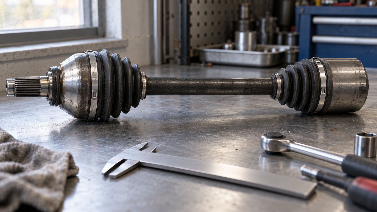
What Is f08-2203020hd? Right CV Axle Assembly Explained
f08-2203020hd is the part number for a complete right-hand front constant velocity (CV) axle assembly — the driveshaft that carries torque from the transaxle to the right front wheel on Jetour X90 and X90 Plus applications. HJDP, the own brand of Jinan Huayuan Auto Bearing Co., Ltd. sold through jnhjdp.com, supplies it as a finished unit: outer fixed joint, inner plunge joint, shaft, both boots, clamps and grease. Spline count, installed length, joint diameters and tone-ring details must be confirmed against the drawing and a physical sample before any stock order.
What Is f08-2203020hd in the Driveline?
f08-2203020hd is a complete right-hand halfshaft, not a bearing, a bare joint or a boot kit — it is the assembled part that bolts between the transmission output and the right front hub.
On a transverse front-wheel-drive powertrain the engine, gearbox and differential sit off the vehicle centreline, so the two driveshafts are deliberately unequal in length. The right shaft and the left shaft are mirror-image parts with separate numbers: the left-hand counterpart f08-2203010hd is a different assembly and cannot be substituted by rotating the right-hand part. Each shaft must do two jobs at once: transmit torque smoothly while the wheel steers, and change its effective length as the suspension compresses and rebounds. That double duty is why the assembly carries two different joint designs rather than two identical ones.
What does a complete assembly include?
- Outer fixed joint at the wheel end, articulating with the steering knuckle.
- Inner plunge joint at the gearbox end, sliding in and out of the differential.
- Shaft, solid or tubular depending on the design and torque level.
- Two boots and their clamps, plus the specified grease charge.
- Retaining circlip that locks the inner joint into the side gear.
- ABS tone ring or machined trigger surface where wheel speed is read at the joint rather than at the hub.
A hub nut and a gearbox oil seal are not part of every assembly. Confirm what the kit contains on the drawing and order fasteners separately, because a reused torque-to-yield hub nut or a hardened gearbox seal is a frequent cause of a repeat repair.
Why do the letters after f08-2203020 change the part?
The numeric core identifies the axle family; the trailing letters mark variants. Assemblies sharing a core number can differ in shaft length, joint size, boot compound, damper fitment or tone-ring configuration, so the suffix is a label rather than a specification. The f08-2203020fl right CV axle assembly and the f08-2203020ab right CV axle assembly both serve a right-hand front position on the same model family, yet they are not automatically interchangeable. Only the drawing and a measured sample tell you which one belongs in a given vehicle.
How Is a CV Axle Assembly Built?
A CV axle assembly carries two different joint designs because the wheel end and the gearbox end face different motion.
At the wheel end the joint must articulate through the full steering angle while rotating at wheel speed. At the gearbox end the joint must let the shaft lengthen and shorten by tens of millimetres as the suspension moves, while the shaft stays roughly parallel to the ground. A fixed joint cannot plunge and a plunge joint cannot steer, so the two functions are split between the two ends of one shaft.
What does the outer fixed joint do?
The outer joint is a constant-velocity ball joint, usually of the Rzeppa type: an inner race on the shaft, an outer bell, and six balls held in a cage. The cage keeps every ball in the bisecting plane of the joint angle, which is what allows the output speed to equal the input speed at any steering angle instead of surging twice per revolution as a simple universal joint would. Ball grade, groove curvature and surface finish set the noise level and the service life, and the boot is the only thing keeping the grease in place.
What does the inner plunge joint do?
The inner joint is normally a tripod design: a three-legged spider on the shaft, with rollers running in tracks inside the housing, allowing axial plunge with a small amount of angularity. Double-offset ball joints appear where lower vibration is a priority. Because the rollers reciprocate in the tracks under load, this end is sensitive to grease condition and is the first place to show a cyclic vibration when lubrication is lost.
Which materials and heat treatment decide service life?
Shafts are machined from medium-carbon or low-alloy steel, with splines and seal journals induction hardened; balls, races and cages are case-hardened or through-hardened so they hold their profile under repeated contact stress. Boots are moulded from thermoplastic polyester elastomer or chloroprene rubber, and the grease is typically a molybdenum disulphide lithium soap type chosen for sliding contact. Two assemblies can look identical from the outside while differing in exactly these details, so ask for the material and heat-treatment notes on the drawing rather than judging by appearance.
How much play should a new joint have?
A new assembly should articulate smoothly by hand with light, even resistance and no notchy points or binding. A small amount of rotational backlash at the splines is normal; a joint that feels gritty, clicks when rocked, or drops freely into a detent is not. Check both ends before installation, because a shaft that is stiff on the bench will usually be noisy in service.
Which Variant Fits Which Vehicle and Duty Cycle?
Fitment is decided by measured dimensions and spline data, not by the vehicle name alone.
One platform can carry several shaft specifications across model years, engines and transmissions, and aftermarket catalogues frequently collapse them into a single listing. The HJDP catalogue entry for f08-2203020hd is indexed against Jetour X90 and X90 Plus applications with a 7DCT and 1.6T designation, while the right CV axle assembly listed for X70, X70 Plus, X70S, X70M and X95 is a different shaft. Treat any catalogue application as a filter for the first enquiry, then confirm with the drawing.
Which measurements should you compare first?
- Side and orientation — left and right are separate parts, not mirrors you can swap.
- Overall installed length, measured between the same datum faces used on the drawing.
- Spline data — tooth count, major diameter, tooth form and effective spline length at both ends.
- Hub interface — thread size and pitch at the outer end, or the bolt pattern where the joint bolts to the hub.
- Tone ring — tooth count and position where wheel speed is sensed at the joint.
- Damper — presence, position and mass of any tuned mass bonded to the shaft.
- Transmission variant, since two gearboxes in the same model can use different inner joints.
How does duty cycle change the specification?
Operating conditions decide which detail matters most. In dusty Gulf and North African markets, fine grit attacks boot folds and clamp seating long before the steel wears out, so boot compound and clamp type deserve more attention than a headline torque figure. In humid tropical markets, water ingress through a pinched boot causes pitting rather than abrasion. Rough-road and loaded use increases plunge travel and boot flex, and stop-go city use shortens joint life through heat cycles. Where one part number serves several markets, ask which boot specification the drawing calls for.
| Parameter | Why it decides fitment | How to verify |
|---|---|---|
| Installed length | Too long bottoms out the plunge joint; too short pulls the circlip | Measure against the drawing datum faces, not overall box size |
| Spline count and diameter | Wrong spline will not enter the hub or the side gear correctly | Count teeth and measure across the major diameter |
| Tone ring | Wrong tooth count triggers ABS and stability faults | Count teeth; confirm ring position on the joint body |
| Inner joint housing | Must match the differential seal bore and circlip groove | Trial fit the sample into the gearbox with the seal in place |
| Damper | Missing or moved mass changes a resonance at cruising speed | Compare position and mass against the drawing |
How Do You Read the Drawing for This Axle?
A usable drawing dimensions the shaft as an assembly and calls out every interface that touches the vehicle.
Catalogue photographs cannot be measured and a part number alone does not define a shaft. Read the drawing in this order: overall length and the datum faces it is measured between; spline callouts at both ends, including tooth form and effective length; the thread or bolt pattern at the hub end; the tone ring callout; boot groove positions and clamp type; damper position and mass; material and heat-treatment notes; marking and grease fill. If any of these is missing, the drawing is not complete enough to order against.
Why is a sample still needed after the drawing?
A drawing describes nominal geometry, while a vehicle accepts a tolerance stack. Revisions, market-specific variants and supplier differences all show up at the interfaces: spline fit into the hub, circlip groove position, boot clearance to the strut or subframe. Measure the sample at those interfaces and do a trial fit before committing to a container load. Sample confirmation is not a formality; it is the step that catches a variant mix-up before it becomes a stock problem.
What Causes These Axles to Fail and How Do You Diagnose It?
Most CV axle failures begin with a damaged boot, not with the steel.
Once a boot splits, centrifugal force throws grease out and grit in. The joint then runs dry and abrasive, and the hardened surfaces that once made it quiet begin to pit. A shaft that fails early and one that lasts the life of the vehicle usually differ in boot integrity and grease retention far more than in steel grade, which is why incoming inspection of boots and clamps is worth more than a visual check of the shaft.
What are the common failure modes?
- Boot cracking in the flex folds, often hidden until the shaft is turned.
- Loose, displaced or missing clamps allowing grease to escape.
- Brinelled races and rollers after a period of running dry.
- Spline wear at the hub end, heard as a single clunk on throttle changes.
- A weakened circlip letting the inner joint walk out of the differential.
- Damper rubber separating from the shaft, producing a drone at cruise.
- A bent shaft after kerb or pothole impact, felt as a once-per-revolution vibration.
Which symptoms point to the axle rather than the hub bearing?
A rhythmic click that rises with wheel speed and is loudest on full lock is the classic outer joint signature. A vibration that appears under acceleration and fades when you lift off points to the inner joint, a worn damper or a damaged shaft. A single clunk on throttle application or release usually comes from spline or circlip play. A steady hum or growl that changes when the steering wheel is loaded and unloaded, and persists in a straight line at constant speed, is more typical of a wheel hub bearing — the two faults are often confused because both are heard from the same corner of the car.
| Symptom | Most likely cause | Quick check on the lift |
|---|---|---|
| Clicking on full lock at low speed | Outer fixed joint wear | Rock the joint by hand; look for split boot folds |
| Vibration under acceleration, gone on coast | Inner plunge joint or damper | Check roller play and damper bonding |
| Clunk on throttle on/off | Spline or circlip play | Check axial movement at the hub splines |
| Grease spray on the inner wing | Boot or clamp failure | Inspect both boots and clamp seating |
| Hum that changes with steering load | Wheel hub bearing | Compare noise left and right while loaded |
What Should Goods-In Inspection Cover?
Goods-in inspection should prove two things quickly: the assembly matches the drawing, and it survived the journey.
- Carton condition — crushed boxes mean a shaft may have taken a point load.
- Part marking — compare the marking on the joint body with the drawing and the invoice.
- Boots and clamps — look for splits, pinches and clamps seated in their grooves.
- Hand articulation — smooth resistance at both joints, no notch or bind.
- Splines and threads — no burrs, no rust, protective coating intact.
- Circlip presence — a missing circlip stops an installation before it starts.
- Measured length — spot-check against the drawing rather than trusting the label.
Keep one unit per batch as a reference sample, sealed and labelled. It settles later disputes about length, spline form or boot type far faster than photographs.
How Should a CV Axle Assembly Be Installed and Replaced?
The sequence matters as much as the part: most premature failures after an otherwise correct replacement come from a reused circlip, a stretched hub nut or a boot twisted during fitting.
- Verify the assembly against the drawing — side, length, spline count and tone ring — before starting.
- With the vehicle on the ground and the brakes applied, loosen the hub nut half a turn.
- Raise and support the vehicle, remove the wheel, and separate the suspension and steering joints required by the workshop manual.
- Release the outer joint from the hub, using a proper puller rather than hammering on the joint body.
- Support the shaft and withdraw the inner joint from the gearbox in a straight line; never let it hang on the seal.
- Inspect the gearbox seal and replace it if worn, and remove any stuck circlip from the side gear.
- Clean the hub splines and the differential bore, and remove corrosion without removing material.
- Fit the new assembly with a new circlip, seating the inner joint fully until it locks.
- Reconnect the suspension and steering joints, then torque the hub nut to the specified figure with the vehicle on its wheels.
- Check wheel alignment where the procedure disturbed it, and road test through full lock in both directions.
What should be replaced at the same time?
Replace the circlip and the hub nut as a matter of course, and any stretch bolt removed during the job. A leaking gearbox seal should be renewed with the shaft out, since a second strip-down costs more than the seal. Where the opposite boot is already cracked, replacing that shaft in the same visit avoids a second labour charge on the same corner.
FAQ: f08-2203020hd and CV Axle Assemblies
Is f08-2203020hd the same as the left-side axle?
No. f08-2203020hd is a right-hand front assembly, and the left-hand position uses a separate part with its own number and length. The two are not interchangeable, even where the joints look similar, because shaft length, damper fitment and sometimes joint size differ. Always confirm the side on the drawing before ordering.
Can I replace only the joint or the boot instead of the whole assembly?
Sometimes, but it depends on condition. A boot that has only just split, with no noise and no play, can often be re-greased and re-booted. Once a joint clicks or shows play, the hardened surfaces are already damaged and a full assembly is the more reliable repair. Confirm what the drawing and sample support before quoting either option.
How do I tell a worn CV joint from a worn wheel hub bearing?
Listen to when the noise appears. A CV joint clicks in rhythm with wheel rotation and is loudest on full lock or under hard acceleration. A hub bearing hums steadily with road speed and changes when the steering wheel is loaded left or right. A lift inspection of boot condition and joint play usually settles the question.
Can HJDP supply this axle with custom packaging or my own brand?
Yes. HJDP, the own brand of Jinan Huayuan Auto Bearing Co., Ltd. at jnhjdp.com, supports drawing and sample confirmation, custom packaging and private-label marking for importers and wholesale channels. Specification, marking content and packing details are agreed in writing against the drawing before production.


