42410-02170 Rear Wheel Hub Assembly: What Buyers Should Check
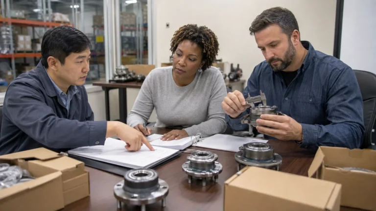
42410-02170 is a rear wheel hub assembly reference in the Toyota-group 42410 series, and it is a complete sealed hub unit, not a bare bearing: flange, bearing rows, seals, grease and, where the drawing specifies it, the ABS encoder arrive as one matched assembly. The practical conclusion for importers and workshop buyers is that the number identifies a family rather than a specification, because bore, flange, stud pattern, encoder position and overall height still have to be confirmed against the drawing and a physical sample. HJDP, the brand of Jinan Huayuan Auto Bearing Co., Ltd. at jnhjdp.com, lists this reference with its dimensional data.
What Is 42410-02170 and What Job Does It Do on the Vehicle?

42410-02170 is a rear axle hub unit: it locates the wheel, carries the rear share of vehicle weight and the braking forces, and provides the machined face on which the brake drum or disc and the wheel sit. A rear unit usually works inside simpler suspension geometry than a front strut hub, so the housing interface and the flange geometry matter more than the surrounding hardware.
Where the part sits and what loads it carries
The hub is the only rotating interface between the road wheel and the suspension, and three load paths pass through it. Vertical load comes from the rear share of kerb weight plus payload and is applied as a radial force on the bearing rows. Lateral load appears during cornering and reverses direction, so the two rows are loaded alternately, which is why a worn rear hub often makes more noise in one direction of turn than the other. Brake torque reaction is transmitted through the hub flange into the friction surface. On a driven rear axle the hub also carries drive torque through a splined or bolted joint to the halfshaft; on a non-driven beam or trailing-arm axle it is a pure bearing carrier. That difference decides which bearing design is appropriate and how the axle nut must be treated during installation.
What a sealed rear hub unit contains
A sealed rear hub unit contains six functional groups, and each one is a potential cause of a fitment or noise complaint if it is reproduced inaccurately.
- An outer ring with the mounting flange that bolts to the knuckle, axle housing or carrier.
- Two rows of rolling elements — balls in most passenger-car units, tapered rollers in heavier applications — each retained by a cage.
- An inner ring assembly, or a pair of inner rings, carrying the hub flange and the wheel studs.
- An outboard seal and an inboard seal, usually dual-lip, retaining grease and excluding water and grit.
- A measured grease fill for life, so the unit is not serviceable and must not be topped up.
- Where an ABS sensor reads at the wheel, a magnetic encoder ring integrated into the seal or fitted to the inner ring.
Why an OE-style number is not a specification
An OE-style number identifies an application family; it does not define the dimensions. In Toyota-group parts numbering the 42410 prefix is applied to rear axle hub and bearing assemblies and the suffix distinguishes individual variants, so two references that share a prefix can differ in flange offset, stud count or encoder position. Importers who order on the number alone are relying on the supplier’s cross-reference rather than on measured data. The safe routine is to request the drawing for the exact reference, compare it with the part being replaced, and confirm with a sample before the first bulk order. The dimensional data for the 42410-02170 rear wheel hub assembly is published for exactly that comparison.
Which Generation of Wheel Hub Unit Is 42410-02170 — Gen 1, Gen 2 or Gen 3?
Rear hub references of this type are most often supplied as Generation 2 or Generation 3 units, but the same family appears in Generation 1 form on older axles, so the generation must be read from the drawing instead of assumed from the number. The three generations differ in where the flange sits, how the bearing is preloaded, and whether the ABS encoder is part of the unit.
| Generation | Structure | Bearing arrangement | Mounting method | Preload and service note |
|---|---|---|---|---|
| Generation 1 | Bearing cartridge only, no flange | Double row, separate inner rings | Pressed into hub or knuckle; shaft passes through | Clearance or preload set by the axle nut; needs a press and a setting procedure |
| Generation 2 | Bearing with flange on the outer ring | Double row ball or tapered roller | Bolted to knuckle or axle housing, three or four fasteners | Preload set at manufacture; not adjustable; encoder may be separate |
| Generation 3 | Bearing and hub flange combined in one unit | Double row ball, sometimes tapered roller | Outer flange bolted to knuckle; inner ring carries wheel studs | Sealed for life; encoder usually integrated into the inboard seal |
The generation decides the installation method, the tooling a workshop needs, and the failure modes you should expect, so it is the first attribute to settle when a buyer builds a rear-axle range. The same logic applies across the family, whether the reference is a Toyota application or a Daihatsu one such as the 42410-B2050 rear hub assembly.
How to identify the generation from a drawing or a sample
Count the flanges. A Generation 1 unit has no flange at all and looks like a thick bearing ring with seals on both faces. A Generation 2 unit has one flange, on the outer ring, and the rotating member is a separate shaft or stub axle. A Generation 3 unit has two flanges: one bolted to the knuckle and one carrying the wheel studs, with the two joined only through the bearing rows. If a sample shows a flange with studs and a bolt circle on the same body, it is Generation 3; if the studs are on a separate hub pressed into a bearing, it is not.
How Do You Read the Drawing Before You Confirm an Order?

Read the drawing from the mounting face outward, because the mounting face is the datum from which every other dimension is referenced. A drawing that quotes only an overall diameter and a bore is not sufficient to confirm a rear hub unit, and a supplier who cannot supply the flange and stud data is asking the buyer to take the risk.
The dimensions that decide whether the part fits
- Flange pilot diameter — centres the wheel or brake disc; if it is undersized the wheel will not seat and run-out appears as vibration.
- Stud or bolt pitch circle diameter and count — defines the wheel fixing pattern; a mismatch makes the part unusable regardless of bearing quality.
- Stud thread and press-in height — controls clamp load and nut engagement; a short stud or a rolled thread of the wrong class will not hold torque.
- Overall height and flange offset — positions the disc or drum relative to the caliper or brake shoes; an offset error shows up as pad rub or a disc that will not centralise.
- Bearing envelope diameter, for press-fit designs — sets the interference fit in the carrier; too loose and the outer ring spins, too tight and the housing cracks.
- Encoder position and sensor bore — fixes the air gap the ABS sensor sees; the wrong position gives an intermittent warning light rather than an obvious mechanical fault.
- Seal outer diameter and lip design — determines how well the unit excludes water; a nominal match with the wrong lip profile fails early in wet or dusty service.
- Material and hardness callout — sets fatigue life; a correct-looking part in the wrong steel grade spalls at low mileage.
Tolerance, clearance and preload
Tolerance on the bearing envelope and the flange faces is what separates a hub unit that runs quietly for its full design life from one that hums within a few thousand kilometres. On Generation 2 and Generation 3 units the internal clearance is set during assembly and cannot be adjusted in service, so the clearance group has to be correct at the factory; the only setting the installer controls is the axle nut torque and its locking method. On Generation 1 units the axle nut does set the preload, which is why the workshop manual figure and the staking procedure matter. When a drawing quotes a tolerance class for the bearing envelope, ask which class is quoted rather than assuming it matches the original part.
| Parameter | What it controls | How a mismatch shows up |
|---|---|---|
| Flange pilot diameter | Concentric location of wheel and disc | Wheel will not seat; run-out and steering-wheel vibration |
| Stud pitch circle and count | Wheel fixing pattern | Wheel cannot be fitted at all |
| Overall height and offset | Brake disc or drum position | Pad rub, uneven wear, caliper contact |
| Bearing envelope diameter | Interference fit in the carrier | Spinning outer ring or cracked housing |
| Encoder position and sensor bore | ABS air gap | Intermittent ABS warning, signal loss at low speed |
| Seal lip profile and diameter | Contamination exclusion | Early water ingress, grease loss, rumble |
| Hardness and steel grade | Rolling contact fatigue life | Spalling and brinelling at low mileage |
Tapered or Cylindrical Roller — Which Bearing Design Suits Which Rear Axle?
Tapered roller bearings suit rear hubs that must take combined radial and axial load within one compact unit, while cylindrical roller bearings suit high radial load where axial location is provided by other components. Both designs appear in automotive running gear, and neither is inherently superior; the correct choice follows the load case on the drawing.
| Attribute | Tapered roller bearing | Cylindrical roller bearing |
|---|---|---|
| Load direction | Combined radial and axial, one direction per row | Predominantly radial, high capacity |
| Typical hub use | Driven axles, light commercial and heavier passenger cars | Non-driven rear axles and shafts needing high radial stiffness |
| Setting | Requires defined preload or end play | Clearance set by adjacent components |
| Stiffness under cornering | High, because the contact angle resists lateral load | High radially, low axially without a thrust face |
| Common failure signature | Spalling on the large rib or cup raceway | Raceway fatigue from misalignment or edge loading |
Material and heat treatment
Hub bearings are normally made from through-hardening bearing steel of the 100Cr6 or GCr15 type, hardened and tempered to a rolling-contact hardness in the high fifties to low sixties on the Rockwell C scale, with races and rolling elements finished to a fine surface roughness. Flanges are commonly produced from medium-carbon steel, either forged or machined from bar, with the bearing seat induction hardened where the drawing calls for it. Cages are usually glass-fibre reinforced polyamide for passenger-car units or steel for heavier applications. The heat treatment record matters more than the steel name, because the same grade can be under-hardened, over-hardened or insufficiently tempered, and each of those errors produces a different failure pattern in the field.
Sealing, grease and the ABS encoder
Sealing decides the service life of a sealed hub unit as much as the steel does, because water and de-icing salt destroy a raceway long before fatigue would. Automotive hub seals are generally nitrile or hydrogenated nitrile lip seals with an additional dust lip, running on a ground surface on the inner ring; a worn or grooved running surface lets the lip lift and the unit loses grease while taking in grit. Grease is a lithium-complex or polyurea type selected for the operating temperature of the brake corner, filled to a measured quantity and sealed for life. Where the encoder is integrated into the seal, the magnetic track must sit at the correct axial position and must not be touched, cleaned with solvent or dropped, since a cracked or magnetically damaged ring produces an ABS fault that looks like a sensor failure.
How Should a Rear Hub Assembly Be Installed and Replaced?
Installation discipline decides whether a correct part performs correctly, because most early hub failures on replaced units trace back to pressing or hammering on the wrong surface rather than to the bearing itself. The sequence below applies to bolted Generation 2 and Generation 3 units and should be adapted to the workshop manual for the specific axle.
- Record the ABS sensor routing and brake hardware position, and disconnect the sensor connector before disturbing the hub.
- With the wheel on the ground and the brakes applied, loosen the axle nut where one is accessible.
- Raise and support the vehicle, remove the wheel, then remove the caliper and disc or drum and suspend the caliper so the hose is not loaded.
- Remove the axle nut and draw the hub off with the specified puller; never strike the flange, the studs or the outer ring.
- Clean the knuckle bore or stub axle and inspect for fretting, corrosion, scoring or out-of-round before fitting anything new.
- Fit the new unit squarely and draw it in with a tool that bears on the correct ring only — on the inner ring for a press-fit bearing, on the flange bolt circle for a bolted unit.
- Torque the mounting bolts or axle nut to the figure on the drawing or in the workshop manual, in stages, then stake or lock as specified.
- Refit the brake components, reconnect the ABS sensor, and verify the sensor air gap where the design allows adjustment.
- Rotate the hub by hand and check end play and flange run-out with a dial gauge before the road test.
- Road test, then re-check fastener torque and repeat the play check at the interval the manual specifies.
Points that decide whether the new unit stays quiet
Three details account for most comebacks. First, the mating faces must be clean and flat: a chip or a film of corrosion on the knuckle face tilts the unit and produces run-out that no bearing can absorb. Second, force must never travel through the rolling elements, so pressing on the flange or dropping the unit onto a bench damages raceways before it is even fitted. Third, the axle nut torque and locking method must follow the manual, because an under-torqued nut lets the inner ring fret on the shaft and an over-torqued one can distort the cage. Replacing the nut rather than reusing it is normal practice on torque-to-yield fasteners.
What Are the Common Failure Modes and How Do You Diagnose Them?
Rear hub failures fall into a small number of recognisable patterns, and each pattern points to a different root cause, so diagnosis should start with the symptom rather than with the part number. Separating a bearing noise from a tyre, brake or differential noise takes a load-transfer road test before anything is dismantled.
| Symptom | Probable cause | Diagnostic check |
|---|---|---|
| Rumble that rises with road speed and changes when cornering | Raceway spalling or brinelling | Load-transfer road test, then hand-spin with the wheel raised and listen at the hub |
| Visible play when the wheel is rocked at twelve and six o’clock | Worn bearing rows or a loose axle nut | Dial gauge end play compared with the drawing; inspect nut torque and staking |
| ABS warning light, intermittent or speed-dependent | Damaged encoder ring, metallic debris, wrong air gap | Inspect the magnetic track for cracks and contamination; check gap and sensor output |
| Grease weeping at the seal | Lip damage, grooved running surface, blocked vent | Examine the seal seat for a wear groove and the lip for hardening or tearing |
| Vibration at speed immediately after replacement | Flange run-out, damaged mating face, wrong pilot diameter | Measure flange run-out with a dial gauge and check both mating faces for flatness |
| Failure within a few thousand kilometres | Installation damage, incorrect nut torque, mixed components | Review the installation record and examine the raceways for indentation patterns |
Matching the symptom to the cause
A noise that changes when the vehicle is loaded from one side to the other is a bearing symptom, because the load transfer changes which row is carrying the wheel. A noise that tracks road surface rather than speed is usually a tyre. A single-wheel ABS fault that appears only at low speed is usually an encoder or air-gap problem rather than a hydraulic one. And a hub that fails very early almost always carries installation damage, which is visible as a line of indentations across the raceway where rollers were forced over a hardened surface — a pattern that cannot be produced by normal service.
What Should You Check When the Shipment Arrives?
Goods-inward inspection for a rear hub unit is a measurement task, not a visual one, and three samples per lot compared against the drawing will catch most of the errors that cause field returns. Keep the measuring record with the lot so a later complaint can be traced to a batch.
- Compare part number, batch or lot marking and quantity on each box against the packing list.
- Measure flange pilot diameter, pitch circle, overall height and bearing envelope on three pieces and record the values.
- Check stud thread with a go/no-go gauge and confirm press-in height and stud squareness.
- Rotate each sampled unit by hand: it should turn smoothly with no roughness, no seal rub and no play beyond the drawing limit.
- Inspect seal lips for cuts or inversion, and encoder rings for cracks, correct axial position and freedom from metallic debris.
- Check preservative coating and packaging for corrosion or deformation caused in transit, especially on machined faces.
Documentation and traceability
Ask the supplier which documents accompany the lot before the first order, so expectations are set in advance rather than at the claims stage. A dimensional inspection report and a material and hardness record for the heat number are reasonable requests for a safety-related running-gear part, and an OEM programme will usually expect a fuller submission file. Batch marking on the unit itself, not only on the box, is what makes traceability possible once the packaging has been opened on the workshop floor.
Frequently Asked Questions About 42410-02170
Is 42410-02170 a wheel bearing or a complete hub assembly?
It is a complete rear hub assembly, meaning the bearing rows, flange, seals, grease and usually the ABS encoder are supplied as one matched unit. That is why it is replaced as a whole rather than pressed apart and re-shimmed, and why the flange and stud dimensions matter as much as the bearing bore when confirming a purchase.
Can a hub with the same number fit a different model year?
Possibly, but the number alone does not prove it. Production changes can alter flange offset, stud count or encoder position while the reference stays in the same family. Confirm fitment against the drawing and a physical sample of the part being replaced, and treat any vehicle list as a starting point rather than as confirmation.
Why does a newly installed rear hub make noise?
Most early noise after replacement comes from installation rather than from the part: a contaminated or damaged mating face, force applied through the rolling elements during fitting, an under-torqued or over-torqued axle nut, or a seal lip damaged on the shaft. A dial-gauge run-out and play check usually separates these from a genuine bearing defect.
Does HJDP supply this reference with custom packaging or private label?
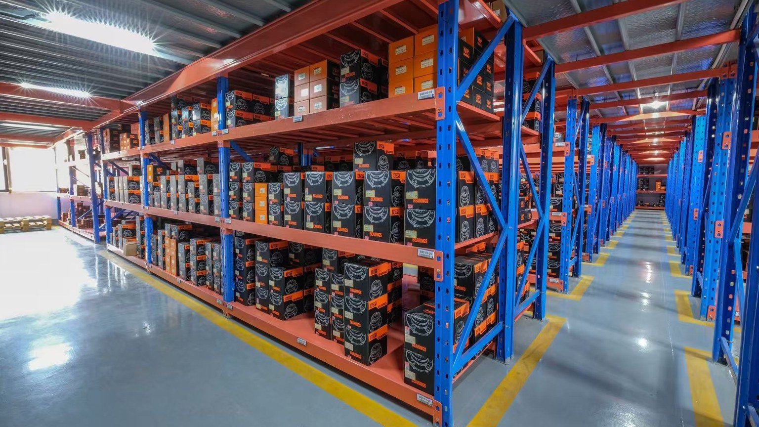
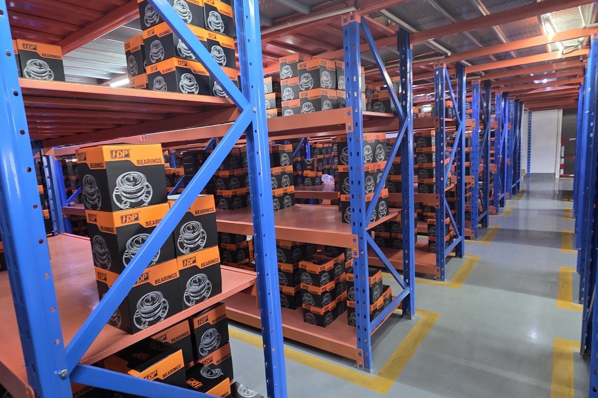
Yes. HJDP is the own brand of Jinan Huayuan Auto Bearing Co., Ltd., and the company offers drawing and sample confirmation, custom packaging and own-brand labelling for importers, wholesale distributors and parts chains. Specification, marking and packaging details for a given order are agreed in writing before production, and the reference is listed at jnhjdp.com.